Potapov's perpetual motion machine. All the details about the manufacture of vortex heat generators with your own hands. For its manufacture it is necessary
Yu. S. Potapov's heat generator is very similar to the vortex tube of J. Ranke, invented by this French engineer back in the late 20s of the XX century. While working on the improvement of cyclones for cleaning gases from dust, he noticed that the gas jet leaving the center of the cyclone has a lower temperature than the source gas supplied to the cyclone. Already at the end of 1931, Ranke filed an application for an invented device, which he called a "vortex tube". But he manages to get a patent only in 1934, and then not in his homeland, but in America (US Patent No. 1952281.)
The French scientists then treated this invention with distrust and ridiculed the report of J. Ranke, made in 1933 at a meeting of the French Physical Society. For according to these scientists, the work of the vortex tube, in which the air supplied to it was divided into hot and cold streams as a fantastic "Maxwell's demon", contradicted the laws of thermodynamics. Nevertheless, the vortex tube worked and later found wide application in many areas of technology, mainly for obtaining cold.
We are most interested in the work of Leningrader V. E. Finko, who drew attention to a number of paradoxes of the vortex tube while developing a vortex gas cooler to obtain ultralow temperatures. He explained the process of gas heating in the near-wall region of the vortex tube by the “mechanism of wave expansion and compression of gas” and discovered the infrared radiation of the gas from its axial region, which has a band spectrum, which later helped us understand the operation of the Potapov vortex heat generator.
In the Ranke vortex tube, the diagram of which is shown in Figure 1, the cylindrical tube 1 is connected at one end to the volute 2, which ends with a nozzle inlet of rectangular cross section, which ensures the supply of compressed working gas into the tube tangentially to the circumference of its inner surface. From the other end, the volute is closed by a diaphragm 3 with a hole in the center, the diameter of which is significantly less than the inner diameter of pipe 1. Through this hole, a cold gas flow exits pipe 1, which is divided during its vortex movement in pipe 1 into cold (central) and hot (peripheral) parts. The hot part of the flow, adjacent to the inner surface of the pipe 1, rotates, moves to the far end of the pipe 1 and leaves it through the annular gap between its edge and the adjusting cone 4.
Figure 1. Ranke vortex tube: 1-tube; 2- snail; 3- diaphragm with a hole in the center; 4 - adjusting cone.
A complete and consistent theory of the vortex tube still does not exist, despite the simplicity of this device. “On the fingers” it turns out that when the gas is untwisted in the vortex tube, it is under the action of centrifugal forces compressed at the walls of the pipe, as a result of which it heats up here, as it heats up when compressed in a pump. And in the axial zone of the pipe, on the contrary, the gas experiences rarefaction, and then it cools, expanding. By removing the gas from the near-wall zone through one hole, and from the axial zone through the other, the initial gas flow is separated into hot and cold flows.
Liquids, unlike gases, are practically incompressible. Therefore, for more than half a century, it never occurred to anyone to supply water to the vortex tube instead of gas or steam. And the author decided on a seemingly hopeless experiment - he fed water from the water supply into the vortex tube instead of gas.
To his surprise, the water in the vortex tube split into two streams with different temperatures. But not hot and cold, but hot and warm. For the temperature of the "cold" flow turned out to be slightly higher than the temperature of the source water supplied by the pump to the vortex tube. Careful calorimetry showed that such a device generates more thermal energy than is consumed by the electric motor of the pump that supplies water to the vortex tube.
So the Potapov heat generator was born.
Heat generator design
It is more correct to speak about the efficiency of the heat generator - the ratio of the amount of thermal energy generated by it to the amount of electrical or mechanical energy consumed by it from the outside. But at first, the researchers could not understand where and how excess heat appears in these devices. It has even been suggested that the law of conservation of energy is violated.

Figure 2. Scheme of a vortex heat generator: 1-injection pipe; 2- snail; 3- vortex tube; 4- bottom; 5- flow straightener; 6- fitting; 7- flow straightener; 8- bypass; 9 - branch pipe.
The vortex heat generator, the scheme of which is shown in Figure 2, is connected with an injection pipe 1 to the flange of a centrifugal pump (not shown in the figure), which supplies water under a pressure of 4-6 atm. Getting into the snail 2, the water flow itself twists in a vortex motion and enters the vortex tube 3, the length of which is 10 times greater than its diameter. The swirling vortex flow in pipe 3 moves along a helical spiral near the pipe walls to its opposite (hot) end, ending in bottom 4 with a hole in its center for the hot flow to exit. In front of bottom 4, a braking device 5 is fixed - a flow straightener made in the form of several flat plates radially welded to a central sleeve coaxial with pipe 3. In the top view, it resembles feathered bombs or mines.
When the vortex flow in pipe 3 moves towards this straightener 5, a counterflow is generated in the axial zone of pipe 3. In it, the water, also rotating, moves to the fitting 6, cut into the flat wall of the volute 2 coaxially with the pipe 3 and designed to release the "cold" flow. In nozzle 6, the inventor installed another flow straightener 7, similar to brake device 5. It serves to partially convert the rotational energy of the "cold" flow into heat. And the warm water leaving it was directed through the bypass 8 to the hot outlet pipe 9, where it mixes with the hot stream leaving the vortex tube through the straightener 5. From the pipe 9, the heated water enters either directly to the consumer or to the heat exchanger (everything about), transferring heat to the consumer circuit. In the latter case, the waste water from the primary circuit (already at a lower temperature) returns to the pump, which again feeds it into the vortex tube through pipe 1.
After careful and comprehensive tests and checks of several copies of the YUSMAR heat generator, they came to the conclusion that there were no errors, the heat is really more than the mechanical energy input from the pump motor that supplies water to the heat generator and is the only external energy consumer in this device.
But it was not clear where the "extra" heat comes from. There were assumptions about the hidden huge internal energy of vibrations of the "elementary oscillators" of water released in the vortex tube, and even about the release of the hypothetical energy of the physical vacuum in its non-equilibrium conditions. But these are only assumptions, not supported by specific calculations confirming the experimentally obtained figures. Only one thing was clear: a new source of energy had been discovered and it looked like it was, in fact, free energy.
In the first modifications of thermal installations, Yu. S. Potapov connected his vortex heater, shown in Figure 2, to the outlet flange of an ordinary frame centrifugal pump for pumping water. At the same time, the entire structure was surrounded by air (If anything about air heating the house with your own hands) and was easily accessible for maintenance.
But the efficiency of the pump, as well as the efficiency of the electric motor, is less than one hundred percent. The product of these efficiencies is 60-70%. The rest is losses that go mainly to heat the ambient air. But the inventor sought to heat water, not air. Therefore, he decided to place the pump and its electric motor in water to be heated by a heat generator. For this, a submersible (borehole) pump was used. Now the heat from heating the motor and pump was no longer given off into the air, but to the water that needed to be heated. This is how the second generation of vortex heating plants appeared.
Potapov's heat generator converts part of its internal energy into heat, or rather part of the internal energy of its working fluid - water.
But let's get back to serial thermal installations of the second generation. In them, the vortex tube was still in the air on the side of the thermally insulated vessel, in which the downhole motor-pump was immersed. From the hot surface of the vortex tube, the surrounding air was heated, taking away part of the heat intended for heating the water. It was necessary to wrap the pipe with glass wool to reduce these losses. And in order not to deal with these losses, the pipe was immersed in the vessel in which the motor and pump are already located. This is how the last serial design of a water heating installation appeared, which received the name YUSMAR.

Figure 3. Scheme of the YUSMAR-M heat plant: 1 - vortex heat generator, 2 - electric pump, 3 - boiler, 4 - circulation pump, 5 - fan, 6 - radiators, 7 - control panel, 8 - temperature sensor.
Installation YUSMAR-M
In the YUSMAR-M unit, a vortex heat generator complete with submersible pump placed in a common vessel-boiler with water (see Figure 3) so that the heat loss from the walls of the heat generator, as well as the heat released during the operation of the pump electric motor, also went to heat the water, and were not lost. Automation periodically turns on and off the heat generator pump, maintaining the water temperature in the system (or the air temperature in the heated room) within the limits specified by the consumer. Outside, the vessel-boiler is covered with a layer of thermal insulation, which simultaneously serves as sound insulation and makes the noise of the heat generator almost inaudible even directly next to the boiler.
YUSMAR units are designed to heat water and supply it to the systems of autonomous, industrial and administrative buildings, as well as to showers, baths, kitchens, laundries, washes, for heating dryers of agricultural products, pipelines of viscous oil products to prevent them from freezing in frost and other industrial and domestic needs.

Figure 4. Photo of the YUSMAR-M thermal installation
YUSMAR-M units are powered by an industrial three-phase 380 V network, fully automated, supplied to customers complete with everything necessary for their operation and assembled by the supplier on a turnkey basis.
All these installations have the same vessel-boiler (see Figure 4), in which vortex tubes and motor pumps are immersed. different power choosing the most suitable for a particular customer. Boiler vessel dimensions: diameter 650 mm, height 2000 mm. These installations, recommended for use both in industry and in everyday life (for heating residential premises by supplying hot water in water heating batteries), there are specifications TU U 24070270.001 -96 and a certificate of conformity ROSS RU. MHOZ. C00039.
YUSMAR units are used in many enterprises and private households, they have received hundreds of accolades from users. At present already thousands of YUSMAR heating plants are successfully operating in the CIS countries and a number of other countries in Europe and Asia.
Their use is especially beneficial where gas pipelines have not yet reached and where people are forced to use electricity to heat water and space heating, which is becoming more and more expensive every year.

Figure 5. Scheme of connecting the thermal installation "YUSMAR-M" to the water heating system: 1 - heat generator "YUSMAR"; 2 - circular pump; 3-control panel; 4 - thermostat.
YUSMAR heat installations allow saving one third of the electricity that is needed for water heating and space heating traditional methods electric heating.
Two schemes for connecting consumers to the YUSMAR-M heat plant have been worked out: directly to the boiler (see Figure 5) - when the hot water consumption in the consumer's system is not subject to sudden changes (for example, for heating a building), and through a heat exchanger (see Figure 6 ) - when the consumption of water by the consumer fluctuates over time.
YUSMAR heating installations do not have parts that heat up to temperatures above 100°C, which makes these installations especially acceptable in terms of fire safety and safety technology.

Figure 6. Scheme of connecting the YUSMAR-M thermal installation to the shower room: 1-heat generator YUSMAR; 2 - circulation pump; 3- control panel; 4 - temperature sensor, 5 - heat exchanger.
Have you noticed that the price of heating and hot water has increased and do not know what to do about it? The solution to the problem of expensive energy resources is a vortex heat generator. I will talk about how a vortex heat generator is arranged and what is the principle of its operation. You will also learn whether it is possible to assemble such a device with your own hands and how to do it in a home workshop.
A bit of history
The vortex heat generator is considered a promising and innovative development. Meanwhile, the technology is not new, since almost 100 years ago, scientists were thinking about how to apply the phenomenon of cavitation.

The first operating experimental plant, the so-called "vortex tube", was manufactured and patented by the French engineer Joseph Rank in 1934.
Rank was the first to notice that the air temperature at the entrance to the cyclone (air cleaner) differs from the temperature of the same air jet at the exit. However, at the initial stages of bench tests, the vortex tube was tested not for heating efficiency, but, on the contrary, for air jet cooling efficiency.

The technology received a new development in the 60s of the twentieth century, when Soviet scientists guessed to improve the Rank tube by launching liquid into it instead of an air jet.
Due to the greater, in comparison with air, density of the liquid medium, the temperature of the liquid, when passing through the vortex tube, changed more intensively. As a result, it was experimentally established that the liquid medium, passing through the improved Rank pipe, warmed up anomalously quickly with an energy conversion coefficient of 100%!
Unfortunately, there was no need for cheap sources of thermal energy at that time, and the technology did not find practical application. The first operating cavitation installations designed to heat a liquid medium appeared only in the mid-1990s.

A series of energy crises and, as a result, an increasing interest in alternative energy sources caused the resumption of work on efficient converters of the energy of the movement of a water jet into heat. As a result, today you can buy an installation of the required power and use it in most heating systems.
Operating principle


Cavitation allows not to give heat to water, but to extract heat from moving water, while heating it to significant temperatures.

The device of operating samples of vortex heat generators is outwardly simple. We can see a massive engine to which a cylindrical "snail" device is connected.
"Snail" is a modified version of Rank's pipe. Due to the characteristic shape, the intensity of cavitation processes in the cavity of the "snail" is much higher in comparison with the vortex tube.

In the cavity of the "cochlea" there is a disk activator - a disk with a special perforation. When the disc rotates, the liquid medium in the “snail” is activated, due to which cavitation processes occur:
- The electric motor turns the disk activator. The disk activator is the most important element in the design of the heat generator, and it, by means of a direct shaft or by means of a belt drive, is connected to the electric motor. When the device is turned on in the operating mode, the engine transmits torque to the activator;
- The activator spins the liquid medium. The activator is designed in such a way that the liquid medium, getting into the disk cavity, twists and acquires kinetic energy;
- Converting mechanical energy into heat. Leaving the activator, the liquid medium loses its acceleration and, as a result of sharp braking, the cavitation effect occurs. As a result, the kinetic energy heats the liquid medium up to + 95 °C, and the mechanical energy becomes thermal.
Scope of application
| Illustration | Description of the scope |
 |
Heating. Equipment that converts the mechanical energy of water movement into heat is successfully used for heating various buildings, from small private buildings to large industrial facilities. By the way, on the territory of Russia today one can count at least ten settlements where centralized heating is provided not by traditional boiler houses, but by gravitational generators. |
 |
Domestic hot water heating. The heat generator, when connected to the network, heats the water very quickly. Therefore, such equipment can be used to heat water in an autonomous water supply system, in swimming pools, baths, laundries, etc. |
 |
Mixing immiscible liquids. Under laboratory conditions, cavitation units can be used for high-quality mixing of liquid media with different densities until a homogeneous consistency is obtained. |
Integration into the heating system of a private house
In order to use a heat generator in a heating system, it must be introduced into it. How to do it right? In fact, there is nothing difficult in this.

In front of the generator (in the figure marked with the number 2) a centrifugal pump is installed (in the figure - 1), which will supply water with a pressure of up to 6 atmospheres. After the generator is installed expansion tank(in the figure - 6) and shutoff valves.
Advantages of using cavitation heat generators
| Advantages of a vortex source of alternative energy | |
 |
Economy. Due to the efficient consumption of electricity and high efficiency, the heat generator is more economical in comparison with other types of heating equipment. |
 |
Small dimensions compared to conventional heating equipment of similar power. Stationary generator suitable for heating small house, twice as compact as modern gas boiler.
If you install a heat generator in a conventional boiler room instead of a solid fuel boiler, there will be a lot of free space. |
 |
Light installation weight. Due to the low weight, even large high-power plants can be easily placed on the floor of the boiler room without building a special foundation. There are no problems at all with the location of compact modifications.
|
 |
Simple design. The cavitation-type heat generator is so simple that there is nothing to break in it. The device has a small number of mechanically moving elements, and there is no complex electronics in principle. Therefore, the likelihood of a breakdown of the device, in comparison with gas or even solid fuel boilers, is minimal. |
 |
No need for additional modifications. The heat generator can be integrated into an existing heating system. That is, it will not be necessary to change the diameter of the pipes or their location. |
 |
No need for water treatment. If a running water filter is needed for the normal operation of a gas boiler, then by installing a cavitation heater, you can not be afraid of blockages. Due to specific processes in the working chamber of the generator, blockages and scale do not appear on the walls. |
 |
The operation of the equipment does not require constant monitoring. If for solid fuel boilers you need to look after, then the cavitation heater works offline. The operating instructions for the device are simple - just turn on the engine in the network and, if necessary, turn it off. |
 |
Environmental friendliness. Cavitation installations do not affect the ecosystem in any way, because the only energy-consuming component is the electric motor. |
Schemes for the manufacture of a cavitation type heat generator
In order to make an operating device with our own hands, we will consider the drawings and diagrams of operating devices, the effectiveness of which has been established and documented in patent offices.
| Illustrations | General description of the designs of cavitation heat generators |
 |
General view of the unit. Figure 1 shows the most common layout of a cavitation heat generator. The number 1 denotes the vortex nozzle on which the swirling chamber is mounted. From the side of the swirling chamber, you can see the inlet pipe (3), which is connected to the centrifugal pump (4). The number 6 in the diagram indicates the inlet pipes for creating a counter disturbing flow. A particularly important element in the diagram is the resonator (7) made in the form of a hollow chamber, the volume of which is changed by means of a piston (9). The numbers 12 and 11 indicate the throttles, which provide control of the intensity of the supply of water flows. |
 |
Device with two series resonators. Figure 2 shows a heat generator in which resonators (15 and 16) are installed in series. One of the resonators (15) is made in the form of a hollow chamber surrounding the nozzle, indicated by the number 5. The second resonator (16) is also made in the form of a hollow chamber and is located at the back end of the device in close proximity to the inlet pipes (10) supplying disturbing flows. Chokes marked with numbers 17 and 18 are responsible for the intensity of the liquid medium supply and for the mode of operation of the entire device. |
 |
Heat generator with counter resonators. On fig. 3 shows a rare, but very efficient scheme device in which two resonators (19, 20) are located opposite each other. In this scheme, the vortex nozzle (1) with a nozzle (5) goes around the outlet of the resonator (21). Opposite the resonator marked 19, you can see the inlet (22) of resonator 20. Please note that the output holes of the two resonators are located coaxially. |
| Illustrations | Description of the swirl chamber (Snails) in the design of the cavitation heat generator |
 |
"Snail" cavitation heat generator in cross section. In this diagram, you can see the following details: 1 - housing, which is made hollow, and in which all fundamentally important elements are located; 2 - shaft on which the rotor disk is fixed; 3 - rotor ring; 4 - stator; 5 - technological holes made in the stator; 6 - emitters in the form of rods. The main difficulties in the manufacture of these elements may arise in the production of a hollow body, since it is best to make it cast. Since there is no equipment for metal casting in the home workshop, such a structure, albeit with damage to strength, will have to be welded. |
 |
Scheme of combining the rotor ring (3) and the stator (4). The diagram shows the rotor ring and the stator at the moment of alignment when scrolling the rotor disk. That is, with each combination of these elements, we see the formation of an effect similar to the action of the Rank pipe.
|
 |
Rotary displacement of the rotor ring and stator. This diagram shows the position of the structural elements of the "snail", in which a hydraulic shock occurs (bubble collapse), and the liquid medium is heated. That is, due to the speed of rotation of the rotor disk, it is possible to set the parameters of the intensity of the occurrence of hydraulic shocks that provoke the release of energy. Simply put, the faster the disk spins, the higher the temperature of the water medium at the outlet. |
Summing up
Now you know what a popular and sought-after source of alternative energy is. So, it will be easy for you to decide whether such equipment is suitable or not. I also recommend watching the video in this article.
The well-known classical methods of generating electricity have one significant drawback, which is their strong dependence on the source itself. And even the so-called "alternative" approaches that allow you to extract energy from natural resources such as wind or Sun rays, are not without this drawback (see photo below).
In addition, the traditionally used resources (coal, peat and other combustible materials) run out sooner or later, forcing developers to look for new options for generating energy. One of these approaches involves the development of a special device, which in the circle of specialists is called a self-powered generator.
Operating principle
The category of generators that use self-feeding, it is customary to include the following names of original designs, which have recently been increasingly mentioned on Internet pages:
- Various modifications of the Tesla free energy generator;
- Energy sources of vacuum and magnetic fields;
- The so-called "radiant" generators.
Among lovers non-standard solutions much attention is paid to the well-known circuit solutions of the great Serbian scientist Nikola Tesla. Inspired by his proposed non-classical approach to using the capabilities of the e / magnetic field (the so-called "free" energy), natural scientists are looking for and finding new solutions.
Known devices that, according to the generally accepted classification, belong to such sources, are divided into the following types:
- The previously mentioned radiant generators and the like;
- Blocking system complete with permanent magnets or transgenerator (with its appearance can be seen in the figure below);

- So called " heat pumps", working due to the temperature difference;
- A vortex device of a special design (another name is the Potapov generator);
- Systems for electrolysis of aqueous solutions without energy pumping.
Of all these devices, the rationale for the principle of operation exists only for heat pumps, which are not generators in the full sense of the word.
Important! The presence of an explanation of the essence of their work is due to the fact that the technology of using the temperature difference has long been used in practice in a number of other developments.
It is much more interesting to get acquainted with a system that works on the principle of radiant transformation.
Overview of radiant generators
Instruments of this type operate similarly to electrostatic transducers, with one slight difference. It lies in the fact that the energy received from the outside is not all spent on internal needs, but is partially given back to the supply circuit.
The most well-known systems operating on radiant energy include:
- Tesla transmitter-amplifier;
- Classic se generator with extension to blocking btg system;
- A device named for inventor T. Henry Morray.
All new generators, invented by fans of alternative methods of energy production, are able to work on the same principle as these devices. Let's consider each of them in more detail.
The so-called "transmitter-amplifier" is made in the form of a flat transformer connected to an external power source by means of an assembly of spark gaps and electrolytic capacitors. Its feature is the ability to generate standing waves of a special form of e / magnetic energy (it is called radiant), which propagates in the environment and practically does not weaken with distance.
As conceived by the inventor himself, such a device was to be used for wireless transmission of electricity over ultra-long distances. Unfortunately, Tesla did not succeed in carrying out his plans and experiments to the end, and his calculations and schemes were partially lost, and some were later classified. The generator-transmitter circuit is shown in the photo below.
![]()
Any copying of Tesla's ideas did not lead to the desired result, and all installations assembled according to this principle did not provide the required efficiency. The only thing that was achieved in this case was to make a device with a high transformation ratio with your own hands. The assembled product made it possible to obtain an output voltage of the order of hundreds of thousands of volts with a minimum of electricity supplied to it.
CE generators (blockings) and Morrey
The operation of ce generators is also based on the radiant principle of energy conversion, obtained in the self-oscillation mode and not requiring constant pumping. After its launch, the recharge is carried out due to the output voltage of the generator itself and the natural magnetic field.
If a self-made product was launched from a battery, then during its operation, excess energy can be used to recharge this battery (figure below).
One of the varieties of self-powered blocking generators is a transgenerator, which also uses the Earth's magnetic field in its work. The latter acts on the windings of his transformer, and this device itself is simple enough to be assembled with your own hands.
By combining the physical processes observed in ce systems and permanent magnet devices, it is possible to obtain blocking generators (photo below).
![]()
Another type of device considered here refers to oldest variants free energy generation schemes. This is a Morrey generator, which can be assembled using a special circuit with diodes and capacitors turned on in a certain way.
Additional Information. At the time of his invention, capacitors in their design resembled the then fashionable electric lamps, however, unlike them, they did not need to heat the electrodes.
Vortex devices
Talking about free sources of electricity, it is imperative to touch on special systems capable of generating heat with an efficiency of more than 100%. This device refers to the previously mentioned Potapov generator.
Its action is based on the mutual vortex effect of coaxially acting liquid flows. The principle of its operation is well illustrated by the following figure (see photo below).

To create the desired water pressure, a centrifugal pump is used, directing it through the pipe (2). In the course of its movement in a spiral near the walls of the housing (1), the flow reaches the reflecting cone (4) and is divided after it into two independent parts.
At the same time, heated outer part the flow returns back to the pump, and its internal component is reflected from the cone with the formation of a smaller vortex. This new vortex flows through the inner cavity of the primary vortex formation, and then enters the outlet of the branch pipe (3) with the heating system connected to it.
Thus, heat transfer is carried out due to the exchange of vortex energies, and the complete absence of mechanical moving parts provides it with a very high efficiency. It is quite difficult to make such a converter with your own hands, because not everyone has special equipment for boring metal.
In modern samples of heat generators operating on this principle, they try to use the phenomenon of the so-called "cavitation". It refers to the process of formation of vaporous air bubbles in a liquid and their subsequent collapse. All this is accompanied by a rapid release of a significant amount of thermal substance.
water electrolysis
When it comes to a new type of electric generators, one should not forget about such a promising direction as the study of the electrolysis of liquids without the use of third-party sources. Interest in this topic is explained by the fact that water is inherently a natural reversible source. This follows from the structure of its molecule, which, as is known, contains two hydrogen atoms and one oxygen atom.
During the electrolysis of the water mass, the corresponding gases are formed, which are used as full-fledged substitutes for traditional hydrocarbons. The fact is that when the gaseous compositions interact, a water molecule is again obtained, plus a significant amount of heat is released along the way. The difficulty of this method is to ensure that the required amount of energy is supplied to the electrolysis bath, sufficient to support the decomposition reaction.
This can be achieved if you change the shape and location of the electrode contacts used, as well as the composition of the special catalyst, with your own hands.
If the possibility of the influence of a magnetic field is taken into account, then it is possible to achieve a significant reduction in the power consumed for electrolysis.
Note! Several similar experiences, proving that, in principle, it is possible to decompose water into components (without additional energy pumping).
The point is small - to master the mechanism that assembles atoms into a new structure (re-synthesizes a water molecule).
Another type of energy conversion is associated with nuclear reactions, which, for obvious reasons, cannot be carried out at home. In addition, they need huge material and energy resources sufficient to initiate the process of nuclear decay.
These reactions are organized in special reactors and accelerators, where conditions are created with a high magnetic field gradient. The problem faced by specialists who are keen on cold fusion of nuclei (CNF) is to find ways to maintain nuclear reactions without additional supply of extraneous energies.
In conclusion, we note that the problem of the devices and systems discussed above lies in the presence of strong opposition from corporate forces whose well-being is based on traditional hydrocarbons and atomic energy. CNS research, in particular, was declared to be an erroneous direction, as a result of which all their centralized funding was completely stopped. Today, the study of the principles of obtaining free energies supported only by enthusiasts.
Video
Greetings to all Seekers!
I receive a lot of letters asking me to clarify the situation with various technologies that we studied in our Laboratory. Here is a letter I received recently, this time by heat generators Potapov and Fominsky:
“Hello Artem. Checked your threads heat generators at "Zaryad" and the test results of heat generators at "",before that, he smoked the “Laboratory 001” forum, contacted Podolyan,talked with Strelkov, by the way he is my countrymanturned out to be, and I’m not happy with him either, but that’s not the point ... heat generators I've been interested since Potapov and Fominsky published an article inmagazine "Inventor and innovator". Then I got the idea to buy or makeheat generator, but so far there was no urgent need to work closely, and nowI study the topic and frankly disappointed. is it so bad?
interesting heat generator Podolyan, but ... not in the drawings of 3 and 4 sheets. Topic on the forum
also died out, Podolyan is not going to share information. The price was announced at 4 thousand bucks,
for me it’s not lifting, and it’s from Ukraine, then he wrote that the company had died and he had
other business.
Can you tell me in which direction to move or with whom and on what forums or in a personal
you can chat on heat generators. We do not have Moscow, we have Siberia, I am from Angarsk.
Sincerely, Vladimir.«
Good afternoon, Vladimir! I understand your interest.
At one time I was also interested in data heat generators and spent a huge amount of time first on collecting information, and then on a “tour” to various objects, communicating with the directors of companies that produce their own versions of these devices. I did not have the slightest doubt about the veracity of the information provided and I really wanted to quickly convey to the whole world the good news about devices that work with KPI=3. In my plans, I have already drawn designs for super-efficient boiler houses that will make a technical revolution. Versions of the nature of super-efficiency were very different, and CNS, and collapsing bubbles, and various ethereal versions, but first of all, it was important for me to use instrumental methods to measure the very CE effect that everyone was talking about. After all, who will buy and use what is not effective? Along the way, various "conspiracy theories" were discussed, explaining the non-recognition of these devices by official science and the fact that they do not receive distribution.
As a result, the heating stand was built, and equipment samples were received. Description and results in the articles of the "cavitation" section of this site.

Unfortunately, no effect was found in these long-term and rigorous tests, and now most of the samples are lying around in the form of a pile of scrap metal.

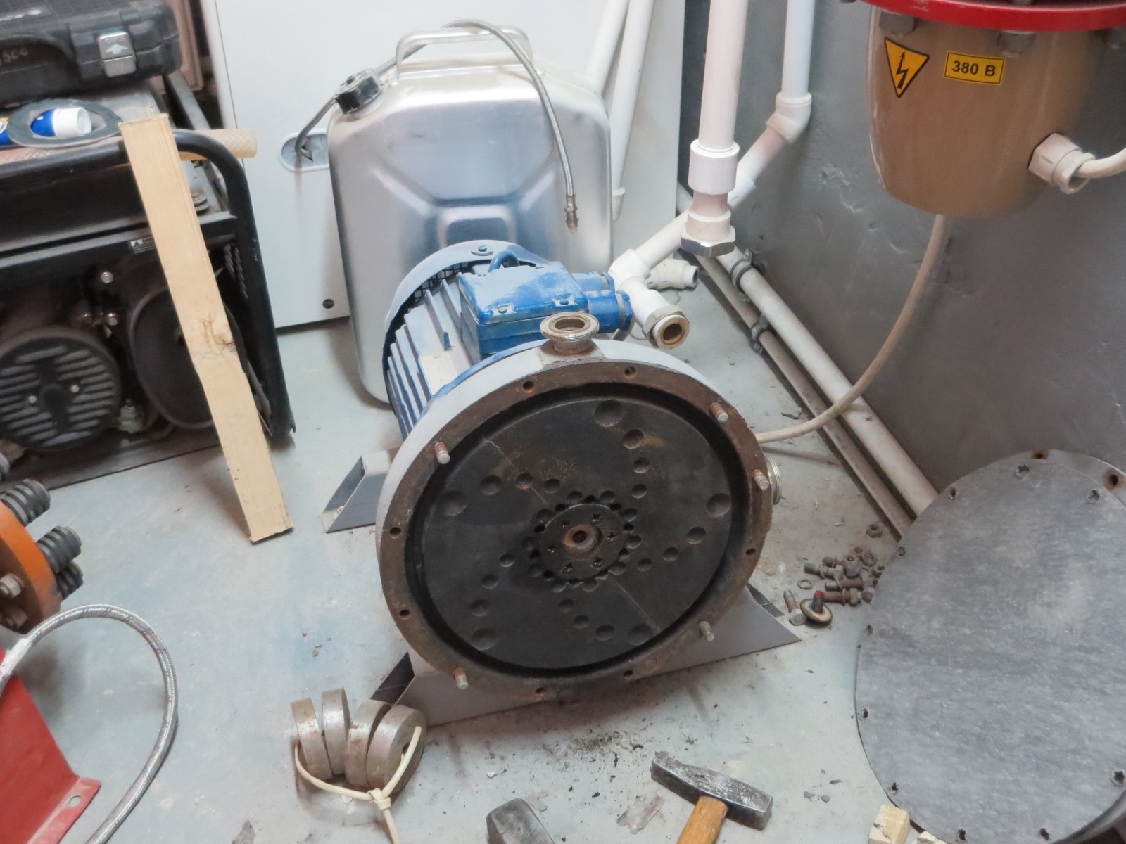
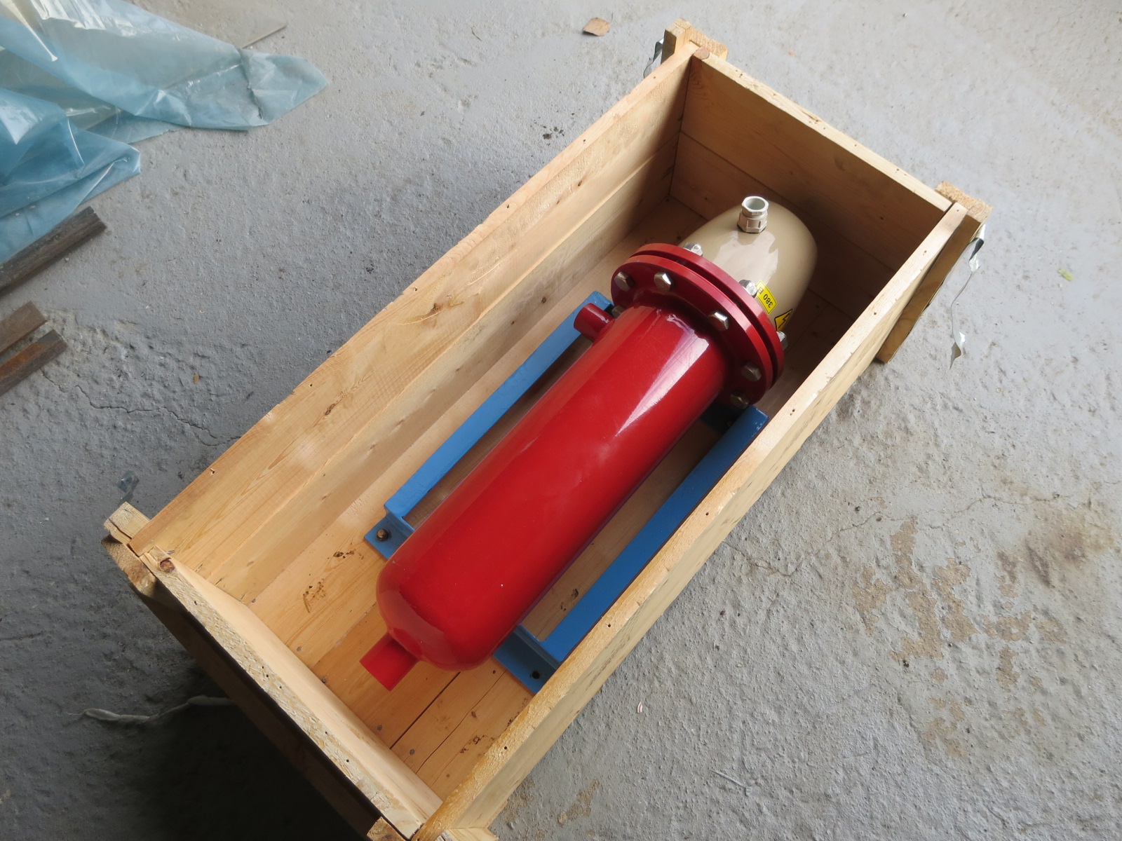
and one is still connected and ready for control launches (here it is with the cover removed):
I must say, some of the manufacturers of this equipment do not hesitate to write directly in the technical data sheet about the thermal power exceeding the consumed electrical power, such as this one (Fisonik, Ensonik technology):
At present, this apparatus, which turned out to be an ordinary electrode boiler, serves to heat the room.
But this apparatus was recently sold by us for experiments with the preparation of fuel for the boiler room:

Here is a page from his technical data sheet, where the declared heat output is higher than the power of the electric motor:
As you can see, manufacturers are not at all embarrassed to write “wonderful” numbers, ”and if you take measurements and don’t find any, there will always be excuses like that everything is not so simple here, it is not possible to measure the effect, and so on.
We took measurements different ways, both with the help of a heat meter and by heating the container

In general, based on the results of long-term tests over 2 seasons, we came to the conclusion that these devices are completely useless, and it is impossible to get any savings using them.
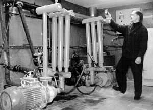
We experienced heat generators Izhevsk plant, as well as the Moscow "NPF TGM", talked a lot with Britvin L.N., visited his laboratory in Moscow, where there is a huge number of various samples:

There were also contacts with Urpin K., director of Teplo 21v, visited their facilities where the data is heat generators, as well as with Kim, the owner of a competitor company selling similar equipment:

It seemed strange to me that with so many orders and objects, the manufacturers of this equipment “didn’t bother” to create a permanent stand. Agree, than to drag potential customers around various objects, it was much easier to show the “goods in person”. Anyway, that's how I would do it.
Heat generators It was not possible to test Strelkov, but we are always ready to test if there is a sample, by the way, Urpin began to sell his products. If anyone has the opportunity, visit the facilities in Angarsk, or bring a sample to us for testing.
In addition, there are many more various types equipment, different manufacturers, similar design - with a rotating rotor.
We did not cover samples where water is heated in a tapering nozzle, or in pipes where water swirls (for example, MUST heat generators)
So, in principle, there is still something to experience;)
As for Podolyan, I don’t have much confidence in his products. Agree, it’s strange: then a person “Smith’s board” was soldered, then suddenly he suddenly became a specialist in heat generators of a completely different type. Recently, according to my observations, Ukraine has become just a "mecca" of CE technologies, which is easily explained by economic problems in this state, and in connection with this - a sharp activation of "enterprising" citizens who are not averse to raising some money on the desire to get cheap heat and electricity. He calls his generator "ethereal" and is not shy about describing his KPI, there are 4, and 5, and above. I am sure that with such technology, this inventor would have already received serious investments, and he would not have been interested in piece assembly for a long time.
Classical devices are often used for heating rooms or heating liquids - heating elements, combustion chambers, filaments, etc. But along with them, devices with a fundamentally different type of effect on the coolant are used. Such devices include a cavitation heat generator, the work of which is to form gas bubbles, due to which heat is released.
Device and principle of operation
The principle of operation of a cavitation heat generator is the heating effect due to the conversion of mechanical energy into thermal energy. Now let's take a closer look at the cavitation phenomenon itself. When excess pressure is created in a liquid, turbulence occurs, due to the fact that the pressure of the liquid is greater than that of the gas contained in it, the gas molecules are released into separate inclusions - the collapse of the bubbles. Due to the pressure difference, water tends to compress the gas bubble, which accumulates a large amount of energy on its surface, and the temperature inside reaches about 1000 - 1200ºС.
When the cavitation cavities pass into the zone of normal pressure, the bubbles are destroyed, and the energy from their destruction is released into the surrounding space. Due to which, thermal energy is released, and the liquid is heated from the vortex flow. The operation of thermal generators is based on this principle, then consider the principle of operation of the simplest version of a cavitation heater.
The simplest model
Rice. 1: Working principle of a cavitation heat generatorLook at Figure 1, here is the device of the simplest cavitation heat generator, which consists in pumping water to the place where the pipeline narrows. When the water flow reaches the nozzle, the liquid pressure increases significantly and the formation of cavitation bubbles begins. When exiting the nozzle, the bubbles emit thermal power, and the pressure after passing through the nozzle is significantly reduced. In practice, multiple nozzles or tubes may be installed to improve efficiency.
Potapov's ideal heat generator
The ideal installation option is Potapov's heat generator, which has a rotating disk (1) installed opposite the stationary one (6). Innings cold water is carried out from the pipe located at the bottom (4) of the cavitation chamber (3), and the removal of the already heated from the upper point (5) of the same chamber. An example of such a device is shown in Figure 2 below:
 Rice. 2: Potapov's cavitation heat generator
 But the device was not widely used due to the lack of practical justification for its operation.
Kinds
The main task of a cavitation heat generator is the formation of gas inclusions, and the quality of heating will depend on their quantity and intensity. In modern industry, there are several types of such heat generators, which differ in the principle of generating bubbles in a liquid. The most common are three types:
- Rotary heat generators- the working element rotates due to the electric drive and generates fluid turbulence;
- Tubular- change the pressure due to the system of pipes through which water moves;
- Ultrasonic– fluid inhomogeneity in such heat generators is created due to low-frequency sound vibrations.
In addition to the above types, there is laser cavitation, but this method has not yet found industrial implementation. Now let's look at each type in more detail.
Rotary heat generator
It consists of an electric motor, the shaft of which is connected to a rotary mechanism designed to create turbulence in the liquid. A feature of the rotor design is a sealed stator, in which heating occurs. The stator itself has a cylindrical cavity inside - a vortex chamber in which the rotor rotates. The rotor of a cavitation heat generator is a cylinder with a set of recesses on the surface, when the cylinder rotates inside the stator, these recesses create heterogeneity in the water and cause cavitation processes to occur.
 Rice. 3: generator design rotary type
The number of recesses and their geometric parameters are determined depending on the model. For optimal heating parameters, the distance between the rotor and the stator is about 1.5 mm. This design is not the only one of its kind; over a long history of upgrades and improvements, the rotor-type working element has undergone a lot of transformations.
One of the first effective models of cavitation converters was the Griggs generator, which used a disc rotor with blind holes on the surface. One of the modern analogues of disk cavitation heat generators is shown in Figure 4 below:
 Rice. 4: disc heat generator
 Despite the simplicity of design, rotary-type units are quite difficult to use, as they require accurate calibration, reliable seals and compliance with geometric parameters during operation, which makes their operation difficult. Such cavitation heat generators are characterized by a rather low service life - 2-4 years due to cavitation erosion of the body and parts. In addition, they create a sufficiently large noise load during the operation of a rotating element. The advantages of this model include high productivity - 25% higher than that of classic heaters.
Tubular
A static heat generator does not have rotating elements. The heating process in them occurs due to the movement of water through pipes tapering in length or due to the installation of Laval nozzles. The water supply to the working body is carried out by a hydrodynamic pump, which creates a mechanical force of the liquid in a narrowing space, and when it passes into a wider cavity, cavitation turbulences occur.
Unlike the previous model, tubular heating equipment does not produce much noise and does not wear out so quickly. During installation and operation, it is not necessary to take care of precise balancing, and in case of destruction heating elements their replacement and repair will be much cheaper than rotary models. The disadvantages of tubular heat generators include significantly lower performance and bulky dimensions.
Ultrasonic
This type of device has a resonator chamber tuned to a certain frequency of sound vibrations. A quartz plate is installed at its input, which produces oscillations when electrical signals are applied. The vibration of the plate creates a wave effect inside the liquid, which reaches the walls of the resonator chamber and is reflected. During the return motion, the waves meet with direct oscillations and create hydrodynamic cavitation.
 Rice. 5: working principle of ultrasonic heat generator
 Further, the bubbles are carried away by the water flow through the narrow inlet pipes of the thermal installation. When passing to a wide area, the bubbles are destroyed, releasing thermal energy. Ultrasonic cavitation generators also have good performance, as they do not have rotating elements.
Application
In industry and in everyday life, cavitation heat generators have found implementation in various fields of activity. Depending on the tasks assigned, they are used for:
- heating- inside the units, mechanical energy is converted into thermal energy, due to which the heated liquid moves through the heating system. It should be noted that cavitation heat generators can heat not only industrial facilities, but also entire villages.
- Running water heating- the cavitation unit is capable of quickly heating the liquid, due to which it can easily replace a gas or electric column.
- Mixing liquid substances- due to the rarefaction in the layers with the formation of small cavities, such units make it possible to achieve the proper quality of mixing of liquids, which naturally do not combine due to different densities.
Advantages and disadvantages
Compared to other heat generators, cavitation units have a number of advantages and disadvantages.
The advantages of such devices include:
- Much more effective mechanism obtaining thermal energy;
- Consumes significantly less resources than fuel generators;
- It can be used for heating both low-power and large consumers;
- Completely environmentally friendly - does not emit in environment harmful substances during work.
The disadvantages of cavitation heat generators include:
- Relatively large dimensions - electric and fuel models are much smaller, which is important when installed in an already operated room;
- Great noise due to the operation of the water pump and the cavitation element itself, which makes it difficult to install it in domestic premises;
- Inefficient ratio of power and performance for rooms with a small quadrature (up to 60m 2 it is more profitable to use an installation on gas, liquid fuel or equivalent electric power with a heating element).\
DIY KTG
Most simple option for implementation at home is a tubular-type cavitation generator with one or more nozzles for heating water. Therefore, we will analyze an example of the manufacture of just such a device, for this you will need:
- Pump - for heating, be sure to choose a heat pump that is not afraid of constant exposure high temperatures. It should provide a working pressure at the outlet of 4 - 12 atm.
- 2 manometers and sleeves for their installation - are placed on both sides of the nozzle to measure the pressure at the inlet and outlet of the cavitation element.
- Thermometer for measuring the amount of heating of the coolant in the system.
- Valve for removing excess air from the cavitation heat generator. Installed at the highest point of the system.
- Nozzle - should have a through hole diameter of 9 to 16 mm, it is not recommended to do less, since cavitation may already occur in the pump, which will significantly reduce its service life. The shape of the nozzle can be cylindrical, conical or oval, from a practical point of view, any will suit you.
- Pipes and connecting elements (heating radiators in their absence) - are selected in accordance with the task, but the simplest option is plastic pipes soldered.
- Automatic switching on / off of the cavitation heat generator - as a rule, it is tied up under temperature regime, is set to turn off at about 80ºС and to turn on when it drops below 60ºС. But you can choose the operating mode of the cavitation heat generator yourself.
 Rice. 6: diagram of a cavitation heat generator
 Before connecting all the elements, it is advisable to draw a diagram of their location on paper, walls or on the floor. Locations must be located away from flammable elements or the latter must be removed to a safe distance from the heating system.
Assemble all the elements, as you have shown in the diagram, and check the tightness without turning on the generator. Then test the cavitation heat generator in the operating mode, the normal increase in liquid temperature is considered to be 3-5ºС in one minute.