Lm317 is an adjustable voltage and current stabilizer. LM317 adjustable voltage and current stabilizer. Characteristics, online calculator, datasheet Lm317t parameters
LM317 Regulated Power Supply Diagram
List of circuit elements:
- Stabilizer LM317
- T1 - transistor KT819G
- Tr1 - power transformer
- F1 - fuse 0.5A 250V
- Br1 - diode bridge
- D1 - diode 1N5400
- LED1 - LED of any color
- C1 - electrolytic capacitor 3300 microfarad * 43V
- C2 - ceramic capacitor 0.1 microfarad
- C3 - electrolytic capacitor 1 microfarad * 43V
- R1 - resistance 18K
- R2 - resistance 220 Ohm
- R3 - resistance 0.1 Ohm * 2W
- P1 - building resistance 4.7K
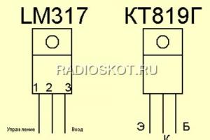
Pinout of the microcircuit and transistor

The case was taken from the computer's power supply. The front panel is made of textolite, it is desirable to install a voltmeter on this panel. I haven't installed it because I haven't found the right one yet. I also installed clips for output wires on the front panel.


The input outlet was left to power the PSU itself. A printed circuit board made for surface mounting of a transistor and a stabilizer microcircuit. I fixed them on a common radiator through a rubber gasket. The radiator took a solid one (you can see it in the photo). It should be taken as large as possible - for good cooling. Still, 3 amps is a lot!

Component references (or datasheets) are essential
in the development of electronic circuits. However, they have one, but an unpleasant feature.
The fact is that the documentation for any electronic component (for example, a microcircuit)
should always be ready before this chip is released.
As a result, we actually have a situation where microcircuits are already on sale,
and yet not a single product based on them has been created.
And, therefore, all the recommendations and especially the application schemes given in the datasheets,
are theoretical and recommendatory in nature.
These circuits mainly demonstrate the working principles of electronic components,
but they have not been tested in practice and should therefore not be blindly taken into account
during development.
This is a normal and logical state of affairs, if only over time and as
accumulating experience, changes and additions are made to the documentation.
Practice shows the opposite - in most cases, all circuit solutions,
given in the datasheet remain at the theoretical level.
And, unfortunately, often these are not just theories, but blunders.
And even more regrettable is the discrepancy between the real (and most important)
chip parameters stated in the documentation.
As a typical example of such datasheets, here is a guide to the LM317,-
three-pin adjustable voltage regulator, which, by the way, is available
already 20 years old. And the schemes and data in his datasheet are still the same ...
So, the shortcomings of the LM317, like microcircuits and errors in the recommendations for its use.
1. Protective diodes.
Diodes D1 and D2 serve to protect the regulator, -
D1 for input short circuit protection and D2 for over discharge protection
capacitor C2 "through the low output impedance of the regulator" (quote).
In fact, diode D1 is not needed, since there is never a situation where
The voltage at the input of the regulator is less than the voltage at the output.
Therefore, diode D1 never opens, and therefore does not protect the regulator.
Except, of course, the case of a short circuit at the input. But this is an unrealistic situation.
Diode D2 can open, of course, but capacitor C2 discharges just fine
and without it, through the resistors R2 and R1 and through the load resistance.
And somehow there is no need to specifically discharge it.
Also, the mention in the Datasheet of "discharge C2 through the output of the regulator"
nothing more than an error, because, as the circuit of the output stage of the regulator -
This is an emitter follower.
And the capacitor C2 simply cannot be discharged through the output of the regulator.
2. Now - about the most unpleasant, namely, the discrepancy between real
electrical characteristics declared.
Datasheets of all manufacturers have an Adjustment Pin Current parameter
(current at the tuning input). The parameter is very interesting and important, determining,
in particular, the maximum value of the resistor in the Adj input circuit.
As well as the value of the capacitor C2. The declared typical current Adj is 50 μA.
Which is very impressive and would completely suit me as a circuit engineer.
If in fact it would not be 10 times larger, i.e. 500 uA.
This is a real discrepancy, tested on chips from different manufacturers.
and for many years.
And it all started with bewilderment - why is it such a low-resistance divider at the output in all circuits?
And that's why it's low-resistance, because otherwise it's impossible to get at the output of LM317
minimum voltage level.
The most interesting thing is that in the technique for measuring the current Adj, the low-resistance divider
the output is also present. Which actually means that this divider is on
in parallel with the electrode Adj.
Only with such a cunning approach can one “fit” into the framework of a typical value of 50 μA.
But this is a rather elegant, but trick. "Special Measurement Conditions".
I understand that it is very difficult to achieve a stable current of the declared value of 50 μA.
So don't write linden in the Datasheet. Otherwise, it is a fraud of the buyer. And honesty is the best policy.
3. More about the most unpleasant.
The Datasheets LM317 has a Line Regulation parameter that defines
operating voltage range. And the range indicated is still not bad - from 3 to 40 volts.
Here is just one small BUT...
The inside of the LM317 contains a current regulator that uses
a zener diode for a voltage of 6.3 V.
Therefore, effective regulation starts with an Input-Output voltage of 7 Volts.
In addition, the output stage of the LM317 is an npn transistor connected according to the circuit
emitter follower. And on the “buildup” he has the same repeaters.
Therefore, efficient operation of the LM317 at a voltage of 3 V is not possible.
4. About circuits that promise to get an adjustable voltage from zero Volt at the output of the LM317.
The minimum voltage value at the output of the LM317 is 1.25 V.
It would be possible to get even less if it were not for the built-in protection circuit against
short circuit at the output. Not the best plan to say the least...
In other microcircuits, the short circuit protection circuit is triggered when the load current is exceeded.
And in the LM317 - when the output voltage drops below 1.25 V. Simple and tasteful -
the transistor closed itself at a base-emitter voltage below 1.25 V and that's it.
That's why, all application schemes that promise to get the output
LM317 adjustable voltage, starting from zero volts - do not work.
All these circuits suggest connecting the Adj pin through a resistor to the source
negative voltage.
But already when the voltage between the output and the Adj contact is less than 1.25 V
the short circuit protection circuit will operate.
All these schemes are pure theoretical fantasy. Their authors do not know how the LM317 works.
5. The output short circuit protection method used in the LM317 also imposes
known restrictions on the launch of the regulator - in some cases, the launch will be difficult,
since it is not possible to distinguish between short-circuit mode and normal-on mode,
when the output capacitor is not yet charged.
6. Recommendations for capacitor ratings at the output of the LM317 are very impressive, -
this range is from 10 to 1000 uF. What in combination with the value of the output resistance
a regulator of the order of one thousandth of an ohm is complete nonsense.
Even students know that the capacitor at the input of the stabilizer is essential,
to put it mildly, more effective than the output.
7. About the principle of regulating the output voltage of LM317.

LM317 is an operational amplifier in which the regulation
output voltage is carried out on the NOT inverting input Adj.
In other words, through the Positive Feedback Circuit (PIC).
Why is it bad? And the fact that all interference from the regulator output through the Adj input passes inside the LM317,
and then back to load. It’s good that the transmission coefficient along the PIC circuit is less than one ...
And then we would get an autogenerator.
And it is not surprising in this regard that it is recommended to put a capacitor C2 in the Adj circuit.
At least somehow filter out interference and increase resistance to self-excitation.
It is also very interesting that in the POS circuit, inside the LM317,
There is a 30pF capacitor. Which increases the level of ripple on the load with increasing frequency.
True, this is honestly shown on the Ripple Rejection chart. But why this capacitor?
It would be very useful if the regulation was carried out along the chain
negative feedback. And in the value of POS, it only worsens stability.
By the way, with the very concept of Ripple Rejection, not everything is “according to concepts”.
In the conventional sense, this value means how well the regulator
filters the ripple from the INPUT.
And for the LM317, it actually means the degree of its own inferiority
and shows how well the LM317 fights ripples, which itself
takes it from the exit and again drives it inside itself.
In other regulators, regulation is carried out along the chain
Negative feedback, which maximizes all parameters.
8. About the minimum load current for LM317.
The Datasheet specifies a minimum load current of 3.5 mA.
At a lower current, the LM317 is inoperative.
A very strange feature for a voltage stabilizer.
So, it is necessary to monitor not only the maximum load current, but also the minimum one too?
This also means that at a load current of 3.5 mA, the efficiency of the regulator does not exceed 50%.
Thank you so much developers...
1. Recommendations for the use of protective diodes for LM317 are of a general theoretical nature and consider situations that do not happen in practice.
And, since it is proposed to use powerful Schottky diodes as protective diodes, we get a situation where the cost of (unnecessary) protection exceeds the price of the LM317 itself.
2. In Datasheets LM317, the parameter for the current input Adj is incorrect.
It is measured in "special" conditions when connecting a low-resistance output divider.
This measurement method does not correspond to the generally accepted concept of "input current" and shows the inability to achieve the specified parameters during the manufacture of the LM317.
And also it is a deception of the buyer.
3. The Line Regulation parameter is specified as a range from 3 to 40 Volts.
In some application circuits, the LM317 "works" at an input-output voltage of as much as two volts.
In fact, the range of effective regulation is 7 - 40 Volts.
4. All circuits for obtaining an adjustable voltage at the output of the LM317, starting from zero volts, are practically inoperative.
5. The LM317 short circuit protection method is sometimes used in practice.
It's simple, but not the best. In some cases, the start of the regulator will be impossible at all.
7. The LM317 implements a flawed principle of output voltage regulation, -
through a positive feedback loop. It should be worse, but nowhere.
8. The limitation on the minimum load current indicates poor circuit design of the LM317 and clearly limits its use cases.
Summing up all the shortcomings of the LM317, recommendations can be made:
a) To stabilize constant "typical" voltages of 5, 6, 9, 12, 15, 18, 24 V, it is advisable to use three-pin stabilizers of the 78xx series, and not LM317.
b) To build truly effective voltage stabilizers, you should use microcircuits like LP2950, LP2951, capable of operating at an input-output voltage of less than 400 millivolts.
Combined with powerful transistors when needed.
The same microcircuits effectively work as current stabilizers.
c) In most cases, an operational amplifier, a zener diode and a powerful transistor (especially a field effect transistor) will give much better parameters than an LM317.
And certainly - the best adjustment, as well as the widest range of types and values of resistors and capacitors.
G). And, don't blindly trust Datasheets.
Any microcircuits are made and, characteristically, sold by people ...
Recently, interest in current stabilizer circuits has grown significantly. And first of all, this is due to the leading positions of artificial lighting sources based on LEDs, for which a stable current supply is a vital point. The simplest, cheapest, but at the same time powerful and reliable current stabilizer can be built on the basis of one of the integrated circuits (IM): lm317, lm338 or lm350.
Datasheet for lm317, lm350, lm338
Before proceeding directly to the circuits, consider the features and technical characteristics of the above linear integrated stabilizers (LIS).
All three IMs have a similar architecture and are designed to build on their basis not complex current or voltage stabilizer circuits, including those used with LEDs. The differences between the microcircuits lie in the technical parameters, which are presented in the comparative table below.
| LM317 | LM350 | LM338 | |
|---|---|---|---|
| Adjustable output voltage range | 1.2…37V | 1.2…33V | 1.2…33V |
| Maximum current load | 1.5A | 3A | 5A |
| Maximum allowable input voltage | 40V | 35V | 35V |
| Indicator of possible stabilization error | ~0,1% | ~0,1% | ~0,1% |
| Maximum power dissipation* | 15-20W | 20-50W | 25-50W |
| Operating temperature range | 0° - 125°C | 0° - 125°C | 0° - 125°C |
| Datasheet | LM317.pdf | LM350.pdf | LM338.pdf |
* - depends on the IM manufacturer.
All three microcircuits have built-in protection against overheating, overload and possible short circuit.
Integrated stabilizers (ICs) are produced in a monolithic package of several options, the most common being the TO-220. The microcircuit has three outputs:
- ADJUST. Output for setting (adjusting) the output voltage. In the current stabilization mode, it is connected to the positive of the output contact.
- OUTPUT. Output with low internal resistance to form the output voltage.
- INPUT. Output for supply voltage.
Schemes and calculations
ICs are most widely used in LED power supplies. Consider the simplest current stabilizer (driver) circuit, consisting of only two components: a microcircuit and a resistor.  The voltage of the power source is applied to the input of the IM, the control contact is connected to the output through a resistor (R), and the output contact of the microcircuit is connected to the anode of the LED.
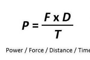
If we consider the most popular IM, Lm317t, then the resistance of the resistor is calculated by the formula: R \u003d 1.25 / I 0 (1), where I 0 is the output current of the stabilizer, the value of which is regulated by the passport data on the LM317 and should be in the range of 0.01 -1.5 A. It follows that the resistance of the resistor can be in the range of 0.8-120 ohms. The power dissipated in the resistor is calculated by the formula: P R \u003d I 0 2 ×R (2). The inclusion and calculations of IM lm350, lm338 are completely similar.
The calculated data obtained for the resistor are rounded up, according to the nominal range.
Fixed resistors are manufactured with a small variation in resistance value, so it is not always possible to obtain the desired output current value. For this purpose, an additional tuning resistor of the appropriate power is installed in the circuit.  This slightly increases the price of the regulator assembly, but ensures that the necessary current is received to power the LED. When the output current stabilizes more than 20% of the maximum value, a lot of heat is generated on the microcircuit, so it must be equipped with a radiator.
Online calculator lm317, lm350 and lm338
Hello. I bring to your attention a review of the integrated linear adjustable voltage (or current) stabilizer LM317 at a price of 18 cents apiece. In a local store, such a stabilizer costs an order of magnitude more, which is why I was interested in this lot. I decided to check what is sold at such a price and it turned out that the stabilizer is quite high quality, but more on that below.
In the review, testing in the mode of a voltage and current stabilizer, as well as checking protection against overheating.
Interested please...
A little theory:
Stabilizers are linear And impulse.Linear stabilizer is a voltage divider, the input of which is supplied with an input (unstable) voltage, and the output (stabilized) voltage is taken from the lower arm of the divider. Stabilization is carried out by changing the resistance of one of the divider arms: the resistance is constantly maintained so that the voltage at the output of the stabilizer is within the established limits. With a large ratio of input / output voltages, the linear stabilizer has a low efficiency, since most of the power Prass = (Uin - Uout) * It is dissipated in the form of heat on the control element. Therefore, the regulating element must be able to dissipate sufficient power, that is, it must be installed on a radiator of the required area.
Advantage linear stabilizer - simplicity, no interference and a small number of parts used.
Flaw- low efficiency, high heat dissipation.
Switching stabilizer voltage is a voltage stabilizer in which the regulating element operates in a key mode, that is, most of the time it is either in cut-off mode, when its resistance is maximum, or in saturation mode - with a minimum resistance, which means it can be considered as a key. A smooth change in voltage occurs due to the presence of an integrating element: the voltage increases as it accumulates energy and decreases as it is returned to the load. This mode of operation can significantly reduce energy losses, as well as improve weight and size indicators, however, it has its own characteristics.
Advantage pulse stabilizer - high efficiency, low heat dissipation.
Flaw- more elements, the presence of interference.
Review hero:
The lot consists of 10 chips in the TO-220 package. The stabilizers came in a plastic bag wrapped with polyethylene foam.


Comparison with probably the most famous 7805 5 volt linear regulator in the same package.


Testing:
Similar stabilizers are produced by many manufacturers, here.
The location of the legs is as follows:  1 - adjustment;
2 - exit;
3 - entrance.
We collect the simplest voltage stabilizer according to the scheme from the manual: 

 Here is what we managed to get with 3 positions of the variable resistor:
  The results, frankly speaking, are not very good. It does not turn out to be called a stabilizer.
Next, I loaded the stabilizer with a 25 Ohm resistor and the picture completely changed: 
Next, I decided to check the dependence of the output voltage on the load current, for which I set the input voltage to 15V, set the output voltage to about 5V with a trimmer resistor, and loaded the output with a variable 100 Ohm wire resistor. Here's what happened:  It was not possible to obtain a current of more than 0.8A, because the input voltage began to drop (the PSU is weak). As a result of this testing, the stabilizer with a radiator heated up to 65 degrees:
To test the operation of the current stabilizer, the following circuit was assembled: 

 Instead of a variable resistor, I used a constant one, here are the test results:
  Current stabilization is also good.
Well, how can a review be without burning the hero? To do this, I assembled the voltage stabilizer again, applied 15V to the input, set the output to 5V, i.e. 10V fell on the stabilizer, and loaded it by 0.8A, i.e. 8W of power was allocated on the stabilizer. Removed the radiator.
The result is shown in the following video:
Yes, overheating protection also works, it was not possible to burn the stabilizer.
Outcome:
The stabilizer is fully operational and can be used as a voltage stabilizer (subject to a load) and a current stabilizer. There are also many different application schemes for increasing output power, using it as a charger for batteries, etc. The cost of the subject is quite acceptable, given that offline I can buy such a minimum for 30 rubles, and for 19 rubles, which is significantly more expensive than the monitored .On this, let me take my leave, good luck!
The product was provided for writing a review by the store. The review is published in accordance with clause 18 of the Site Rules.
I plan to buy +37 Add to favorites Liked the review +59 +88The LM317 is more suitable than ever for the design of simple regulated sources and, for electronic equipment, with various output characteristics, both with regulated output voltage and with a given voltage and current loads.
To facilitate the calculation of the required output parameters, there is a specialized LM317 calculator, which can be downloaded from the link at the end of the article along with the LM317 datasheet.
Specifications of the stabilizer LM317:
- Providing output voltage from 1.2 to 37 V.
- Load current up to 1.5 A.
- The presence of protection against a possible short circuit.
- Reliable protection of the microcircuit from overheating.
- Output voltage error 0.1%.
This inexpensive integrated circuit is available in TO-220, ISOWATT220, TO-3, and D2PAK packages.
The purpose of the pins of the microcircuit:


Online calculator LM317
Below is an online calculator for calculating the voltage regulator based on the LM317. In the first case, based on the required output voltage and the resistance of the resistor R1, the resistor R2 is calculated. In the second case, knowing the resistances of both resistors (R1 and R2), you can calculate the voltage at the output of the stabilizer.
See the calculator for calculating the current stabilizer on the LM317.
Application examples of the LM317 stabilizer (wiring diagrams)
current stabilizer
The current stabilizer can be used in the circuits of various battery chargers or regulated power sources. The standard charger circuit is shown below.
In this switching circuit, the direct current charging method is used. As can be seen from the diagram, the charge current depends on the resistance of the resistor R1. The value of this resistance is in the range from 0.8 ohm to 120 ohm, which corresponds to a charging current from 10 mA to 1.56 A:

5 Volt power supply with electronic switching

Below is a diagram of a 15 volt power supply with a soft start. The necessary smoothness of switching on the stabilizer is set by the capacitance of the capacitor C2:

Switching circuit with adjustable output voltage