Milling machine f. Milling machines with the lower arrangement of a spindle. Designation of console milling machines
24.05.2015
The domestic industry produces single-spindle machines F-4, F-5, F-6, FSH-4 and FA-4. They are used in woodworking enterprises with serial production and in auxiliary production enterprises.
The FSh-4 machine performs tenon-cutting work. Machine FA-4 can be used with manual and mechanical feed. All machines with manual feed are of the same type in design, with the difference only in the modification of individual units.
The basic model is the F-4 milling machine of medium type.
F-6 belongs to light machines with an increased number of revolutions of the spindle. On it, small rectilinear and curvilinear parts are processed according to the template and ruler.
F-5 belongs to heavy machines. Large parts are processed on it according to the template and ruler.
Machines with manual feed are simple in design, with the same type of kinematic scheme, therefore only the F-4 machine is considered in more detail (Fig. 138).
A caliper 3 is mounted on the frame 1 in the guides 2. A spindle 10 is fixed on the caliper by means of ball bearings. The height of the spindle is set by the handwheel 13 using a lifting mechanism consisting of gear a and screw gears. The caliper is fixed with locking screws 5. Table 7 is fixed in the upper part of the bed, and on the table there is a box-section guide ruler 8, which simultaneously serves as a fence for the milling head. To remove dust, a receiver 11 is provided. The spindle drive is from an electric motor 16 through a flat-belt transmission 17. The electric motor is mounted on a pivotally reinforced plate under the engine.
The belt is tensioned by deflecting the under-engine plate and the motor with the drive pulley by means of the handwheel 14. The belt is guarded by a special shield 15. A special cabinet 4 is mounted on the side of the frame to accommodate electrical equipment, and the control buttons are located on the shield 12. Handle 6 is used to turn on the brake of the electric motor.
At high loads in the process of processing large-sized workpieces, it is provided (on the upper part of the spindle) to install an additional support 9, which is mounted on a bracket 18, mounted on the bed.
To prevent vibration, the workpiece during the cutting process is pressed from above by spring-loaded stops 19. The workplace is illuminated by lamp 20.
The main unit of the machine is the bed, which serves as a means of absorbing vibrations arising from the imbalance of the spindle rotating at a high number of revolutions.
The table is the base for the processed workpieces. There is a round hole in the middle of the table for the spindle nozzle to exit. The hole diameter is adjusted by inserting insert rings depending on the diameter of the cutter used. The grooves on the table serve as guides for moving the ruler, fixing the fence, etc.
The caliper is a cast-iron frame of a rigid structure, on the cross members of which the housings of the spindle shaft bearings are cast. The rigid connection of the housings of both (upper and lower) bearings ensures precise boring, and then the installation of single-row high-speed ball bearings.
The extreme sides (vertically) of the caliper are precisely machined and mate with the guides of the bed, along which the caliper is adjusted in height. Caliper movement within 50-100 mm.
The spindle shaft (Fig. 139, a) in the upper part (inside the rod) has a socket with a Morse taper for attaching a spindle attachment, on which the cutter is fixed.
The connection of the spindle shaft with the nozzle must be coaxial and ensure the centering of the axis of the cutter with the shaft-nozzle system. Strengthening of the nozzle on the spindle shaft in compliance with the centering (Fig. 139, b) is carried out using a cap 1 or differential 2 clamping nut. The most perfect is considered to be fastening with a differential nut, which has two threads with different pitches (a large pitch on the spindle, a smaller one on the nozzle rod). With the help of the differential nut, the nozzle is easily pulled out of the spindle seat, and also firmly connects the cones of the nozzle and shaft, creating reliable friction between the cones.
The most critical parts in the spindle shaft assembly are the bearings. They must ensure normal operation at high speeds. In machines with a lower spindle position, single row angular contact ball bearings are predominantly used.
It is unacceptable to install thrust thrust bearings, as they are not suitable for high speed operation.
Of particular importance is the lubrication of high-speed bearings. To do this, a liquid low-viscosity oil is used, fed into the bearings by gravity. Waste oil is supplied by a screw pump back to the tank (Fig. 139, c).
During the operation of machines at high speeds, spindle vibration is observed. The inertial forces arising from the imbalance create additional dynamic loads on the ball bearings, excite vibrations of machine parts and assemblies. Spindle deflection causes machining errors. To reduce the effect of unbalance, it is recommended to install a third support at the end of the spindle. According to LTA research, this support increases the vibration resistance of the spindle assembly by 10 times.
A wide driven pulley is mounted on the cantilevered lower part of the spindle for free movement of the belt; it provides vertical movement of the spindle unit.
The two-spindle machine F2-4 is designed for processing frame and panel parts along the outer contour. To prevent sticking and tearing of wood from the processing surface, a mutually opposite direction of rotation of the cutter heads is provided.
In essence, the F2-4 machine is a dual single-spindle F-4 machine. The machine bed and table are common to both spindles. The design of calipers and spindles, their lubrication and drive systems are the same as for machines F-4, F-5, etc. Each spindle has an independent drive.
Machine tools with mechanized feed
The domestic industry produces a machine with a mechanized feed FA-4. It is a modification of the F-4 machine. The mechanism (Fig. 140, a) with a toothed sprocket ensures the supply of straight and curved workpieces using a special template.
The feed sprocket 1 is mounted on a hollow shaft 2, which is reinforced based on independent rotation relative to the spindle (on ball bearings).
The drive of the sprocket from the electric motor 5, through the gearbox 4 and the chain drive 3. The sprocket 1 engages with the roller chain, which is mounted on the side surface of the template 6. When rotating, the sprocket with teeth through the chain moves the template in the direction of the tangent to the clutch point, feeding in the direction of the profile of the side surface of the template. On the lower side of the template there is a groove 7, the vertical wall of which along the perimeter is parallel to the lateral outer surface of the template. The template is inserted between the feed sprocket and the pressure roller 8. To limit the movement of the template and prevent its excessive pressure on the sprocket, a restrictive ring 9 is installed on the hollow shaft, the roller is pressed against the template by the spring 11. pinch roller 8.
The pressure roller is retracted by pedal 12, thereby the clutch of the sprocket with the roller chain is broken and the feed stops. The milling spindle 13 has a geometric axis with a feed sprocket. Cutter 14 is located above the feed sprocket. The workpiece is pressed against the template by a clamping element with a spherical surface 15, and the pressure on the element is produced by the spring 16.
The clamping element is adjusted in height by moving the bracket 17 along the column 18.
The blanks on the template are fixed by pricking on spikes 19.
The sprocket feed mechanism can be used when processing workpieces along external and internal closed and open contours. This mechanism is mainly used in the processing of heavy parts with a long line of processing of a closed contour and a slightly elongated shape.
In foreign practice, attached mechanisms with rotating templates are used (Fig. 140, b). The mechanism is attached to the machine table. Its design consists of a housing 1 with a gearbox, an electric motor 2, which transmits the movement to the gearbox through a wedge belt drive. To tension the belt, the electric motor is mounted on the sub-plate 3. Two swing frames 4 with spindles 5 are attached to the body. The spindles receive movement from the electric motor through the gearbox. Rotating templates 6 are attached to the spindles from below. The workpiece to be processed is placed under the template. After turning the handle 7, the spindle with the template goes down, pressing the workpiece with spikes, and sets it in motion. Handle 8 serves to bring the frame with the spindle to the cutting tool. The workpiece is processed along the copy surface of the template. This mechanism is used for processing curved workpieces with a thickness of 10-15 mm and a diameter of 130-140 mm along a closed contour.
Copiers
When processing curved surfaces along the outer contour, devices are used (Fig. 141, a), which consist of a template 1, which has a curved side surface 5, corresponding to the part of the workpiece being machined, and a thrust copying ring 2, which has a common axis of rotation with the spindle of the milling head 3. The template consists of a base 4 and a stop 5. It is made of dry hardwood or thick multi-layer plywood (for precision work - made of light duralumin metal). The workpiece 6 is fixed on the template by clamps 7. In the process of machining the workpiece by cutting, the copying edge of the template 8 abuts against the thrust ring 2. This ensures that the contour of the reference side surface of the template is transferred to the surface of the workpiece being machined.
The design of the thrust ring can be of two types. In the first case, the ring is put on the spindle (ball bearing) - fig. 141, b, and in the second - the ring is not connected to the spindle and is fixed in the table (Fig. 141, c). The first design is simple in design, but has a significant drawback: it transfers the transverse force from the template pressure to the spindle. This drawback is deprived of the thrust ring of the second design.
At one of the furniture and woodworking plants, a thrust ring with an adjustable reference diameter was used. It is known that when processing along the contour of the side surfaces of furniture units, it is necessary to observe the correspondence between the cutting diameter of the cutter head and the supporting diameter of the ring. The ring with an adjustable reference diameter significantly reduces machine set-up time and ensures precise machining of the part. The ring (Fig. 141, c) has a round base 1 with a hole for the free passage of the spindle. The upper part of the ring is machined, a thread is cut on the machined surface with a pitch of 2 mm. The ring is fixed on table 2.
An adapter ring 3 is screwed onto the machined part, the outer face of which is beveled at an angle of 15°. Slots for a special key are cut on the upper edge of the adapter ring. The adapter ring is covered by the guide RING 4, the inner face of which is also beveled at an angle of 15°. This ring is split and tightened with the help of specially welded plates with bolt holes. The ring is fixed in the desired position with the help of pin 5 fixed on the base of the ring. Each full turn of the adapter ring changes the outer diameter of the thrust ring by 0.33 mm. In this way, the cutting diameters of the cutter head and thrust ring are matched.
The technical characteristics of milling machines with a lower spindle location are given in Table. 61.
Information about the manufacturer of the console milling machine 6R13F3, 6R13F3-37
Manufacturer of milling vertical console machines 6R13F3, 6R13F3-37 Gorky Plant of Milling Machines founded in 1931.
The second manufacturer of machine tools 6R13F3 Votkinsk Machine-Building Plant VMZ, (currently OAO Votkinsk Plant) founded in 1757 by Count P.I. Shuvalov with the permission of Empress Elizabeth.
The production of vertical console milling machines at the Votkinsk Machine-Building Plant began in 1956, and in 1959 the production of CNC milling machines began.
Today console milling machines are produced by the enterprise LLC "Machine Park" founded in 2007.
Console-milling machines. General information
Console milling machines horizontal and vertical - this is the most common type of machines used for milling work. The console milling machines got their name from the console bracket (console), which moves along the vertical guides of the machine bed and serves as a support for the horizontal movements of the table.
Standard sizes of console milling machines It is customary to characterize by the size of the working (fixing) surface of the table. Console milling machines can have horizontal, universal (wide universal) And vertical execution with the same size of the working surface of the table. The combination of different versions of the machine with the same basic dimensional characteristic of the table is called size range of machines.
In the USSR, the production of console milling machines of five sizes was mastered:
No. 0; No. 1; No. 2; No. 3 and No. 4, and for each size a full range of machines was produced - horizontal, universal and vertical. Each machine of the same size range had the same designation in the cipher, corresponding to the size of the working surface of the table.
Depending on the size of the working surface of the table, the following sizes of console milling machines are distinguished:
| Size | Range of machines | Table size, mm |
|---|---|---|
| 0 | 6R10, 6R80, 6R80G, 6R80Sh | 200 x 800 |
| 1 | 6N11, 6N81, 6N81G; 6R11, 6R81, 6R81G, 6R81Sh | 250 x 1000 |
| 2 | 6M12P, 6M82, 6M82G; 6P12, 6P82, 6P82Sh; 6T12, 6T82, 6T82G, 6T82Sh | 320 x 1250 |
| 3 | 6M13P, 6M83, 6M83G; 6P13, 6P83; 6T13, 6T83, 6T83G | 400 x 1600 |
| 4 | 6M14P, 6M84, 6M84G | 500 x 2000 |
In accordance with the dimensions of the table, the overall dimensions of the machine itself and its main components (bed, table, sled, console, trunk), the power of the electric motor and the magnitude of the greatest movement (stroke) of the table in the longitudinal direction, the sled in the transverse direction and the console in vertical directions change.
Designation of console milling machines
6 - milling machine (group number according to ENIMS classification)
R- series (generation) of the machine (B, K, N, M, R, T)
1 - subgroup number (1, 2, 3, 4, 5, 6, 7, 8, 9) according to the ENIMS classification (1 - vertical milling)
2 - machine version - standard size (0, 1, 2, 3, 4) (3 - desktop size - 400 x 1600)
Letters at the end of the model designation
G– horizontal console-milling machine with a non-rotary table
TO- machine with a copier for processing curved surfaces
B- a machine with increased productivity (increased range of spindle speeds, table feeds and increased power of the main movement engine).
P- machine accuracy - (n, p, c, a, c) according to GOST 8-XX
W– wide universal machine
F1– a machine tool with a digital indication device DRO and a pre-set of coordinates
F2– a machine with a CNC positional numerical control system
F3– machine tool with contour (continuous) CNC system
F4- multi-purpose machine with CNC contouring system and tool magazine
6R13F3 vertical console milling machine with CNC. Purpose and scope
Console milling vertical machine 6R13F3 with CNC was put into production in 1972. Based on this model, 6r13rf3 machines with a turret, 6r13f3-37 were designed.
The 6R13F3 vertical milling machine is designed for processing a variety of complex profile parts made of steel, cast iron, hard-to-cut non-ferrous metals, mainly face and end mills, drills in medium and small-scale production.
The milling machine model 6R13F3-37 is equipped with a CNC device H33-2M, which allows processing products in the program control mode simultaneously in three coordinates: longitudinal and transverse (moving the table and slide with the workpiece) and vertical (moving the slider with the tool).
The principle of operation and design features of the machine
The programmable vertical movement (Z coordinate) is carried out by the movement of the slider. The console of the CNC milling machine 6R13F3 has only an installation movement, excluding positioning and operation in the servo mode of the console, which has a significant mass. The accuracy of processing increases, since the console is always clamped during the cutting process.
The machine is equipped with servo-adjustable feed drives with high-torque DC motors.
The use of adjustable servo drives with DC motors provides a speed of fast movement of the table up to 4.8 m/min and eliminates the rejection of the part during contouring in the event of a feed drive failure along one of the coordinates.
Introduced centralized lubrication guides.
The machine adopts an electromechanical tool clamping device, providing a stable clamping force of 2000 kg.
For remote equipment, ready-made wiring with plug connectors is available.
Roughness of the machined surface Rz = 20 µm.
Machine accuracy class - H according to GOST 8-82.
Developer - Gorky Machine Tool Production Association.
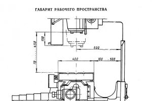
Dimensions of the working space of the milling machine with CNC 6R13F3

Dimensions of the working space of the CNC milling machine 6r13f3-37
Mounting dimensions of the CNC milling machine 6R13F3

Mounting dimensions of the CNC milling machine 6r13f3-37
General view of the milling machine 6R13F3

Photo milling machine 6r13f3-37
6R13F3 Location of the components of the CNC console milling machine


The location of the components of the milling machine 6r13f3-37 with CNC
- Bed - 6R13F3-37.10
- Reducer - 6R13F3-37.25
- Console - 6R13F3-37.61
- Electrical installation box - 6R13F3-37.068
- Table and sled - 6R13F3-37.70
- Electrical equipment - 6R13F3-37.80
- Spindle head - 6R13F3-01.38
- Gearbox - 6R13F3-01.32
- Gearbox - 6R13F3.50
- Guide rail protection - 6R13F3.74
- Cooling - 6R13F3.90
- Fencing - 6R13F3.91
- Protective device - 6M13P.91
The location of the controls of the CNC machine model 6R13F3


The location of the controls of the milling machine 6r13f3-37
List of controls for the 6R13F3 machine and their purpose
- Slider stroke limiting cams
- "Tool release" button
- Tool clamp button
- Toggle switch for turning on the cooling pump
- Toggle switch for turning on the Z coordinate
- Toggle switch for turning on the Y coordinate
- Toggle switch for turning on the X coordinate
- Process stop switch
- Toggle switch for manual and automatic operation
- Feed rate selection switch
- Manual longitudinal movement of the table
- Feed enable toggle switch
- Toggle switch for setting coordinates to zero position
- Program start button
- Node stepping button
- Spindle start button
- Console up button
- Spindle stop button
- Console down button
- Z zero setting cams
- X Coordinate Zeroing Cams
- Console clamp handle on bed
- Longitudinal stroke limiter cams
- All stop button
- speed indicator
- Spindle Jog button
- Shift knob
- Console travel limit cams
- Manual vertical movement of the console
- Handle for lifting and lowering the fence
- Y-coordinate zeroing cams
- Cams limiting the transverse travel of the table
- All stop button
- Manual lateral movement of the table
Kinematic diagram of a CNC milling machine 6R13F3

Kinematic diagram of a CNC milling machine 6r13f3-37
Description of the design of the CNC milling machine 6R13F3
Machine bed
The bed is the main base unit on which the units and mechanisms of the machine are mounted.
The rigid construction of the bed is achieved due to the developed base and a large number of ribs. Its front body has vertical guides along which the console moves. To read the value of the installation movement of the console, a ruler is fixed on the bed.
Limit switches are placed in the left niche of the frame to limit the console travel. In the upper part of the frame housing on the right side there is a window through which access to the oil pump and gearbox is opened. To select the required speed, a gearbox is installed on the left side of the frame. A spindle head is fixed on the mating plane of the bed neck. There is an oil reservoir inside the frame body. The bed is installed on the base and fastened to it with bolts.
Machine speed box
The gearbox is used to tell the spindle various speeds of rotation during cutting.
Lubrication of bearings and gears of the gearbox is carried out from a plunger pump located inside the gearbox.
Gear box
Provides 18 spindle speeds and allows you to select the desired speed without successive passage of intermediate steps.
Switching speeds is carried out as follows: the handle 28 (sheet 14, Fig. 4) is lowered down until the spike of the handle is removed from the locking groove and retracted from itself until it stops. By turning the dial, poz.26 set the required number of revolutions against the arrow pointer. In this case, the click of the latch means that the dial is fixed in this position. Press the push button, pos. 27, return the handle with a smooth movement to its original (initial) position.
Lubrication of the gearbox is carried out from the plunger pump of the gearbox.
Machine spindle head
The spindle head consists of three main elements: a slide, a gearbox, a slider with a spindle.
The slide is centered in the annular undercut of the bed neck and is attached to it with four bolts. A slider with a spindle moves along the rectangular guides of the slide - the Z coordinate.
The gearbox serves to transfer the main (rotational) movement to the spindle from the gearbox through a pair of bevel and three cylindrical wheels.
The movement of the slider with the spindle according to the program is carried out from a high-torque engine through a gearbox from a pair of cylindrical wheels (Fig. 8) and a "rolling screw-nut" transmission.
To carry out manual movement of the slider, an output is provided - a hexagon I (Fig. 7).
Table and sled (Fig. 9,10 and II)
The table and sled provide movement of the table along the X and Y coordinates (longitudinal and transverse).
When moving along the X coordinate, the table receives movement from a high-torque motor of the PBV112LGUZ type through a single-stage gearbox with a gear ratio i = 1:2 and a rolling screw-nut transmission.
Leading ball screw for longitudinal movement of the table rotates in ball bearings mounted on the left side in the bracket, and on the right - in the gearbox housing.
The screw nuts are rigidly fixed in a bracket attached to the table.
In the reducer of the longitudinal movement of the table there is a BTM-1V type transformer, which is a feedback sensor.
The movement of the table to the Y coordinate is carried out from the drive mounted in the console. The running ball screw of the transverse movement of the table is installed in the console housing.
For manual movement of the table there is a hexagonal output 2 (Fig. 9).
The gap in the guides of the table and slide is selected with wedges. To adjust the gap, see section "Adjustment".
CNC milling machine console 6R13F3
The console is the basic unit that combines the drives of the vertical and transverse movements of the table.
Along the vertical guides of the frame (of the dovetail profile, the console provides a vertical installation movement. Along the horizontal guides of the rectangular profile console, the "Table and sled" assembly moves in the transverse direction (Y coordinate).
In the depth of the console, a two-stage gearbox for the transverse movement of the table with a gear ratio i = 1:2 is mounted.
The movement of the table is carried out from a high-torque electric motor of the PBV112LGUZ type through a gearbox and a rolling screw-nut transmission.
Cylindrical helical gears are prefabricated to eliminate side clearance in gearing.
A rotating transformer of the VTM-1B type, pos. 1 (Fig. 13).
On the right side of the console body, an asynchronous electric motor of the 4A90LA type of vertical installation movement is installed. The movement is carried out through a worm pair and a screw gear.
To lubricate the guides of the machine's moving parts, gears and bearings, the console has an oil reservoir and a VT II-IIA type lubrication pump, which is powered by an AOL-21-4 engine.
The horizontal guides of the console are closed in front with telescopic protection, and in the back - with "aprons" attached to the bed and the rear end of the slide.
Machine operation with electromechanical tool clamping
The control of the electromechanical tool clamping device is carried out in the following sequence:
- press button 3 (see fig. 3) "tool clamp";
- turn on the spindle with button 17 "Spindle start"
When pressing the tool, it is necessary:
- turn off the spindle with button 19 and make sure that the spindle stops;
- press button 2 "Tool release" and hold until the milling mandrel leaves the spindle for a length of no more than 15 ... 20 mm.
Otherwise, the splined roller may completely turn out of the rod. Then, when clamping the tool, the rod must be pressed up so that the threaded end of the roller is screwed into the threaded hole of the rod.
Installation of cutters in mandrels is carried out depending on their size and type according to Fig.15,16.
The tool in the mandrel is fixed outside the machine using replaceable ramrods. The mandrel has an outer cone 7:24 and an inner "Morse No. 4" For fastening a tool with Morse cones No. 2,3,5, replaceable adapter bushings 2 and 3 are used. to process with end mills (with a tapered shank) respectively Ø 16, Ø 20, Ø 40, Ø 50.
Capture I must be installed in such a way that its T-slot is perpendicular to the leading grooves of the mandrel.
Insert the mandrels with the tool into the taper hole of the spindle and, by turning at an angle of 90 °, connect to the T-shaped end of the rod, turn on the "Tool Clamp" button. The end of the clamp is determined by pushing the cam clutches.
The clamping of the tool must be carried out at a spindle speed of no more than 40 rpm.
Electrical equipment of the machine 6R13F3. General information
The electrical equipment is located on the machine in the control station and also includes the NZZ-2M numerical control system.
The control station serves to accommodate switching devices, electrical circuit protection devices.
The electrical equipment is powered through the control station from a three-phase alternating current network with a voltage of 380 V, a frequency of 50 Hz. The permissible fluctuation of the supply voltage is 15% ± 10% of 380 V. In case of large fluctuations in the mains voltage, it is necessary to power the CNC device and the electric automation of the machine from a separate stabilizer. It is possible to power a group of CNC machines from a separate stabilizer or a separate machine converter.
The machine uses the following voltages:
- power circuit - three-phase, alternating current 380 V, frequency 50 Hz;
- control circuit - variable 110 V, 50 Hz;
- local lighting circuit - alternating 24 V, 50 Hz;
- control circuit - 24 V DC;
- electrodynamic braking circuit - 55 V DC;
- power supply of feed motors - 48 V DC.
The power supply of the control station is switched on by the Introductory automatic machine (I), which is controlled by means of a handle placed on the door of the control station.
The following drives are installed on the machine:
- electric drive of the main movement; carried out from an asynchronous motor type 4А132S4У3, 7.5 kW, 1450 rpm, 380 V, designation according to the M1 scheme (A02-5I-4, 7.5 kW, 1450 rpm, 220/380 V);
- electric drive for adjustment movement of the console; carried out from an asynchronous motor type 4A90LA, 2.2 kW, 1500 rpm, 380 V, designation according to the scheme M2;
- tool clamp electric drive; is carried out from an asynchronous motor type 4AAS56V4U3, 0.18 kW, 1500 rpm, 380 V, designation according to the M4 scheme;
- cooling pump electric drive; performed from an asynchronous motor XA14-22M (0.12 kW; 2800 rpm; 380 V; designation according to the scheme M3;
- lubrication electric motor type AOL-21-4, 0.27 kW, 1500 rpm; 380 V; designation according to the M5 scheme
- longitudinal feed electric drive (X coordinate) is carried out from a DC electric motor type PBV-112L 2.2 kW 1000 rpm, 110 V, designation according to the M7 scheme.
The feed drive motor is controlled by the CNC through a thyristor converter of the 3T6S-8-PBV-112LU4 type.
The speed feedback is provided by a tachogenerator built into the electric motor with excitation from permanent magnets. Designation according to the scheme M6.
Position feedback is provided by a rotating transformer type BTM-1V
- the electric drive of the transverse feed (Y coordinate, sled) is carried out similarly to the X coordinate. The designation of the devices according to the scheme: electric motor - M9, tachogenerator - M8, rotating transformer - P2;
- vertical feed electric drive (Z coordinate, slider) is carried out similarly to the X coordinate. The designation of the devices according to the scheme: electric motor - M11. tachogenerator - M10, rotating transformer - PZ.
6R13F3 CNC vertical milling machine. Video.
Technical characteristics of the CNC milling machine 6R13F3-37
| Parameter name | 6R13F3-37 | 6R13RF3 |
|---|---|---|
| Accuracy class according to GOST 8-82 | H | H |
| Main parameters of the machine | ||
| Dimensions of the working surface of the table (length x width), mm | 400 x 1600 | 400 x 1600 | 300 | 300 |
| Number of T-slots Dimensions of T-slots | 3 | 3 |
| The greatest longitudinal movement of the table (X), mm | 1000 | 1000 |
| The greatest transverse movement of the table (Y), mm | 400 | 400 |
| The greatest vertical adjustment movement of the table, mm | 420 | 380 |
| Distance from the spindle axis to the vertical guides of the bed (outreach), mm | 500 | 500 |
| The smallest distance from the rear edge of the table to the bed rails, mm | 100 | 100 |
| Distance from the end of the spindle to the working surface of the table, mm | 70..450 | |
| The greatest vertical movement of the slider (Z), mm | 250 | - |
| Working feed limits. Longitudinal, transverse, vertical, mm/min | 3..4800 | 20..1200 |
| Speed of fast movement of a table and a ram, mm/min | 4800 | 2400 |
| The smallest and largest distance from the end of the spindle to the table mm | 70...490 | 70...450 |
| Feed per impulse, mm | 0,01 | 0,01 |
| Positioning accuracy along the X axis, mm | 0,065 | |
| Positioning accuracy along the Y, Z axis, mm | 0,040 | |
| Maximum drilling diameter, mm | 30 | |
| The largest diameter of the end mill, mm | 40 | |
| The largest diameter of the end mill, mm | 125 | |
| Spindle | ||
| Number of spindles | 1 | 6 |
| Spindle speed, rpm | 40...2000 | 40...2000 |
| Number of spindle speeds | 18 | 18 |
| Maximum torque, kgf.m | 62,8 | |
| Spindle end | GOST 836-72, 7:24 | |
| CNC system | ||
| CNC type | H33-2M | H33-1M |
| Dimensioning method | In increments | In increments |
| Types of interpolation | Linear Circular | Linear Circular |
| Number of simultaneously controlled coordinates with linear / circular interpolation | 3/2 | 3/2 |
| electrical equipment | ||
| Number of electric motors on the machine | 8 | |
| Main drive electric motor, kW (rpm) | 7,5 (1450) | 7,5 |
| Electric feed drives along the X, Y, Z axes, kW | 2,2 | stepper |
| Electric drive of adjustment movement of the console, kW | 2,2 | |
| Tool clamp electric drive, kW | 0,18 | - |
| Cooling pump electric drive, kW | 0,12 | |
| Lubrication pump motor, kW | 0,27 | |
| Total power of electric motors, kW | 16,87 | |
| Machine dimension | ||
| Machine dimensions, mm | 3450 x 3970 x 2965 | 3200 x 2500 x 2450 |
| Machine weight, kg | 4450 | 6900 |
CNC vertical milling machine 6R13F3 is intended mainly for the manufacture of various elements from such materials: steel, cast iron, non-ferrous metals (which can be attributed to those that are difficult to process), mainly using milling end and end drills with the expectation of small-scale, as well as medium-scale production.
CNC system 6R13F3
The 6r13f3 device is also characterized by the presence of a passport - a document that describes its capabilities.
The CNC allows processing various kinds of structures in the organization of program control, using at the same time a set of three coordinates:
- perpendicular (movement of the sled and the table with the polished product);
- axial;
- vertical (movement of the slider with the mechanism), so the machine-coded vertical rebase (Z coordinate) is performed by moving the slider.
The protrusion of this milling machine accommodates only the indicated movement, which in turn eliminates the indication and action in the associated load on the console, which has a significant weight. In this way, it is possible to increase the level of manufacturing error, because the beam must be clamped every time during the operation of the machine.
Vertical milling machines are equipped with a vertical shaft, which moves in a vertical direction, in certain samples it has the property of rotation. The table moves both horizontally transversely to the center and vertically.

Machine drives
The supply of the CNC machine 6R13F3 contains servo-adjustable supply gears with electric motors with a high speed of switching on uninterrupted electricity. The use of tracking stabilization movers in combination with motors for continuous or continuous supply of electricity in machine tools guarantees the speed of accurate movement of the table up to 4.8 m/min.
Defects of elements are also excluded in the case of intermittent processing, unless there are defects during the transfer of the delivery along one of the coordinates. You can also introduce a centralized coating of the main elements of machine tools. The use of electromechanical constructions of gripping mechanisms, which guarantees a continuous clamping force of up to 2000 kg, is used quite often. For the purpose of portable supply, a characteristic such as prepared electrical wiring with fork disconnection is applicable.
Name decoding
By studying the passport of the desired machine, you can find the names of the alphanumeric indicator:
- the milling machine indicates the number 6;
- modification of the device - the letter P;
- the vertical milling machine is indicated by the number 1;
- the standard coverage of the mechanism (the size of the table) is determined by the number 3;
- F3 - the presence of the CNC device.
Machine bed
The bed takes the place of the main central link, which contributes to the installation of the primary and automatic structure of the machine.
The solid construction of the frame contributes to an extended foundation and a fair amount of ribs. The frame base accommodates the components of the vertical guidance, the purpose of which is to move the beam. By means of a fixed track on the frame, it is possible to calculate the amount of instructive movement of the arm.
With the help of limit switches it is possible to limit the general direction of the beam in the left-hand area of the cladding recess. On the right side of the cover section of the fuselage of the machine there is a gap, which opens the passage to the oil pump, and also shows the gearbox. The left front of the beam is equipped with a transition box from low speed to high speed in order to select the required pace of work with milling parts. The wire plane of the hole in the bed is fixed with a spindle head. In the middle of the bed is a special oil compartment. The body is mounted to the machine at the base and held with bolts.
Machine speed box
In order to give a signal to the spindle about the required speed during the cutting process, you need to have a gearbox. It will help you manage the machine more efficiently and monitor the speed of milling parts. The gearbox, in fact, “informs” the spindle about the change in the speed of turns when cutting.
It is necessary to lubricate the bearings and gears in the gearbox in the direction from the piston pump, which is located in the middle of this box.
Machine spindle head
The top on the machines has three main components:
- Sled.
- Reducer.
- Slider with shaft.
The sled is aligned with the circular undercut of the neck of the machine and is held with it with four bolts. In this case, the valve with the shaft can be moved towards the rectangular slide guides (Z coordinate).
The gearbox is designed to represent the main circular movement of the spindle using a gearbox, as well as a pair of conical and three cylindrical wheels.
The grouping of the slider with the shaft according to the project is implemented using an engine, as well as a gearbox with two tubular rollers, plus moving the screw to the nut, and the nut to rolling.
Table and sled
These components create favorable conditions for the table to move towards the X and Y coordinates (axial and perpendicular). To begin with, in order for the movable screw to help the table move horizontally, it rotates in ball bearings that are installed on the left side of the holder.
The support also fixes the screw nuts, which are attached to the table. The fractional motion controller has a BTM-1V type converter, the description of which is brought by the inverse interaction controller.
The shift of the table along the Y ordinate is carried out from the mover, which is mounted in the beam. The movable ball screw of the perpendicular movement of the table is located in the frame of the beam. In order to move the table manually, you need to use a hex pin.

Electrical equipment of the machine 6R13F3
The electrical supply is located on the device in the control point and contains some construction of the numerical control “NZZ-2M”. The control point helps to place horizontally installed devices in it to provide an electrical circuit.
The electrical equipment is supplied with the help of a control station from a three-phase alternating current network with a voltage of 380 V, a frequency of 50 Hz. The fluctuation that is allowed at the supply voltage is 15% ± 10% of 380 V.
In case there are large fluctuations in the mains voltage, it is necessary to supply power to the CNC structure and electrical automation, which in turn is a unique equalizer for machines.
The following types of voltage in machine tools are often applicable:
- power circuit - three phases, alternating current 380 V, frequency 50 Hz;
- control circuit - alternating 110 V, 50 Hz;
- local illumination scheme - alternating 24 V, 50 Hz;
- adjustment circuit - constant 24 V;
- electrodynamic tightening circuit - constant 55 V;
- supply of electric power motors - constant 48 V.

Connecting the switch to the control power can be done using the initial installation, which can be controlled by the handle displayed on the door of the control unit.
Feedback in the high-speed direction is carried out through a tachogenerator mounted in an electric motor with motivation from permanent magnets.
It is intended for processing various complex profile parts made of steel, cast iron, hard-to-cut non-ferrous metals, mainly face and end mills, drills in medium and small-scale production.
CNC system
CNC milling machine 6R13F3, 6R13RF3, 6T13F3 was equipped by the manufacturer with a CNC system model NZZ-2M. CNC allows you to process products in the program control mode simultaneously in three coordinates: longitudinal, transverse (moving the table and slide with the workpiece) and vertical (moving the slider with the tool). The programmable vertical movement (Z coordinate) is carried out by the movement of the slider. The console of the CNC milling machine 6R13F3, 6R13RF3, 6T13F3 has only an installation movement, excluding positioning and operation in the tracking mode of the console, which has a significant mass. The accuracy of processing increases, since the console is always clamped during the cutting process.
Machine drives
Equipped with servo-adjustable feed drives with high-torque DC motors. The use of adjustable servo drives with DC motors provides a speed of fast movement of the table up to 4.8 m/min and eliminates the rejection of the part during contouring in the event of a feed drive failure along one of the coordinates. Introduced centralized lubrication guides. The machine adopts an electromechanical tool clamping device, providing a stable clamping force of 2000 kg. For remote equipment, ready-made wiring with plug connectors is available.
Designation
The alphanumeric index of the CNC milling machine 6R13F3, 6R13RF3, 6T13F3 means the following: the number 6 is a milling machine; the letter P, T, M - modification of the machine, number 1 - indicates a vertical milling machine, number 3 - standard size of the machine (table size), F3 - the presence of a CNC system.
| Specifications | Options |
| Dimensions of the working surface of the table, mm | 400 x 1600 |
| Accuracy class according to GOST 8-71 | P |
| Surface roughness Rz, µm | 20 | 300 |
| The greatest longitudinal movement of the table (X), mm | 1000 |
| The greatest transverse movement of the table (Y), mm |
400 |
| The greatest vertical adjustment movement of the table, mm | 420 |
| The greatest vertical movement of the slider (Z), mm | 250 |
| Working feed limits. Longitudinal, transverse, vertical, mm/min | 3 - 4800 |
| Speed of fast movement of a table and a ram, mm/min | 4800 |
| Distance from spindle nose to table, mm | 70 - 490 |
| Distance from the spindle axis to the vertical guides of the frame, mm | 500 |
| Feed per impulse, mm | 0,01 |
| Positioning accuracy along the X axis, mm | 0,065 |
| Positioning accuracy along the Y, Z axis, mm | 0,040 |
| Maximum drilling diameter, mm | 30 |
| The largest diameter of the end mill, mm | 40 |
| The largest diameter of the end mill, mm | 125 |
| Spindle speed, min-1 | 40 - 2000 |
| Number of spindle speeds | 18 |
| Maximum torque, kgf.m | 62,8 |
| Spindle end GOST 836-72 | 7:24 |
| Main drive electric motor, kW | 7,5 |
| Electric feed drives along the X, Y, Z axes, kW | 2,2 |
| Electric drive of adjustment movement of the console, kW | 2,2 |
| Tool clamp electric drive, kW | 0,18 |
| Cooling pump electric drive, kW | 0,12 |
| Lubrication electric motor, kW | 0,27 |
| Total power of electric motors, kW | 16,87 |
| Overall dimensions of the machine (L x W x H), mm | 3450 x 3970 x 2965 |
| Machine weight with electrical equipment, kg | 4450 |
CNC milling machine 6R13F3, 6R13RF3, 6T13F3 today
The CNC milling machine 6R13F3, 6R13RF3, 6T13F3 was produced at the Gorky Plant of Milling Machines. At the same time, other factories of the former USSR also produced machines of this design. Some of them are still working today, producing improved versions of the 6R13F3 CNC milling machine. They are equipped with modern high-quality components and reliable electrics.
Price
Upon request, we can provide a price for modern inexpensive analogues of CNC milling machines 6R13F3, 6R13RF3, 6T13F3. For example, with a table measuring 1050x520 mm, it costs from $71,200.
Modern analogues
Our catalog contains high-quality modern analogues of CNC milling machines 6R13F3, 6R13RF3, 6T13F3 - machines made in the Czech Republic. They have a modern design combined with high quality workmanship. The relatively low price for this level of machines makes TAJMAC-ZPS CNC milling machines one of the best offers in terms of price / quality ratio.
TO Category:
Woodworking machinery
Milling machines with a lower spindle
Design
A single-spindle milling machine with manual feed and with a lower spindle location (Fig. 1) consists of a bed along which the caliper moves vertically. The spindle is fixed in the caliper on ball bearings. For a long nozzle, a bracket with a folding bearing is provided to ensure the stability of the spindle. When changing the tool, the bracket is taken away from the Y side. Guide lines and clamps are installed in the slots of the table. The position of the spindle in height is adjusted with a handwheel.
The electric motor is connected to the spindle by a flat belt transmission. The pulley mounted on the spindle has an elongated shape, which allows you to change the position of the spindle in height without changing the position of the electric motor.

Rice. 1. Milling single-spindle machine F-4: 1 - frame, g - support, 3 - spindle lifting handwheel, 4 - table, 5 - removable ruler guides, 6 - bracket with folding bearing, 7 - receiving funnel, 8 - handwheel for tension belt
A more advanced design has an FSA machine for rectilinear milling (Fig. 2). Just like the F-4 machine, its spindle is mounted on a caliper. The position of the spindle in height is changed with a handwheel. The spindle is connected to the motor shaft by a belt drive, a handwheel is used to tension the belts. An automatic feeder is installed above the machine table. Its feed rollers are hinged, which allows you to feed workpieces with a difference in thickness of up to 20 mm into the machine. If manual feed is required, the automatic feeder can be removed from the machine or set aside (for example, when installing a cutting tool). To change the position of the automatic feeder in the vertical plane, a handwheel is provided. The handwheel connected to the variator sets the feed rate, which can vary between 8-25 mm.
Convenient placement of the control panel allows the machine operator to avoid unnecessary movements during operation.
On fig. 3 shows the kinematic diagram of the FA-4 milling machine with automatic feed. On the spindle, movably, in ball bearings, a block of sprockets is fixed, which rotates independently of the spindle. The workpiece to be processed is placed in a tsulaga and fixed in it. A part of the side surface of the cleat acts as a copier, a bush-roller chain or a perforated tape is fixed on it, corresponding to the teeth of the upper sprocket of the block. The upper sprocket in the process of machine operation comes into engagement with the chain and feeds the clamp with the material being processed along the cutting tool. The upper sprocket is driven by the lower (drive) sprocket of the block, which is connected by a chain drive to the feed mechanism drive, which includes an electric motor, a worm gear and a gear.
The design of the feed mechanism provides for the possibility of imparting a rectilinear movement to the template during one-sided processing of workpieces and rotational when processing along a contour. Details with a contour outlined in a circle are processed with a movable axis of rotation of the template. In all other cases, the contour points of curved parts are at different distances from the cutting circle described by the cutter. Therefore, in order to ensure continuous contact of the workpiece with the cutting tool, it is necessary to change the distance from the center of rotation of the template to the cutting circle. To do this, insert 6 is movably fixed with a finger and a lever is installed that connects the template with the spring. When installing and removing the template, the insert with the finger is removed from the spindle axis by the pedal. If one side of the curved workpiece is processed, then the template is pressed against the feed sprocket by pressure rollers mounted on the insert.

Rice. 2. FSA milling machine: 1 - table, 2 - automatic feeder, 3 - handwheel for setting the feed rate, 4 - handwheel for the height adjustment mechanism of the automatic feeder, 5 - control panel, 6 - handwheel for the spindle height adjustment mechanism, 7 - handwheel for the tension mechanism belts, 8 - frame
Domestic industry also produces FSH-4 milling machines, designed not only for flat and profile milling, but also for picking studs. These machines are equipped with a tenoning carriage, which is movably fixed on special bed rails. Clamps, a stop ruler and end stops are installed on the carriage. Move the carriage manually. The manual movement of the carriage during the modernization of the machine can be mechanized, for example, using a pneumatic cylinder with a hydraulic regulator. Clamps can be equipped with an air motor.

Rice. 3. Kinematic diagram of a single-spindle milling machine FA-4 with automatic feed: 1 - pedal, 2 - spindle support, 3 - handwheel, 4 - cable, 5 - lever, 6 - insert, 7 - finger, 8 - spring, 9 - cutter , 10 - sprocket block, 11 - gear, 12 - worm gear, 13 - feed motor, 14 - spindle motor, 15 - belt tension handwheel
Operating mode selection
The choice of operating mode on milling machines of any design is reduced to determining the feed rate of the workpieces being processed. Milling is often the final operation of machining workpieces, since grinding after milling (especially figured workpieces) is difficult. Therefore, when choosing the operating modes of milling machines, they proceed from the requirements for the roughness of the machined surface. The required surface roughness class depends on the amount of feed and the angle at which the cutter meets the wood fibers.
Example. It is required to determine the feed rate when milling a curved part with a variable meeting angle fvh, which varies from 0 to 30°. The roughness of the machined surface must correspond to the seventh class. The cutter diameter is 120 mm, the number of cutters r = 4, the spindle makes 6000 revolutions per minute.
Machine setup
When milling flat surfaces, the cutting edges of the lower end of the cutter should be located 3-5 mm below the table level, which is achieved by corresponding movement of the spindle. In the case of profile milling, the position of the cutter is determined by the template or sample of the part installed on the machine table.

Rice. 4. Guide rulers of the milling machine: 1 - rear ruler, 2 - bracket, 3 - front ruler
Through flat and profile milling of straight workpieces is performed along the rear and front guide lines (Fig. 4), which are connected by a cast bracket covering the cutting tool. Ruler 1 can be made as one piece with the bracket, the ruler is movably fixed on the bracket. Usually, rulers made of wood are applied to the metal planes of the rulers. The vertical planes of the rulers must be perpendicular to the plane of the machine table.
With flat milling, the back ruler is installed along the bar, with profile milling - using a standard. To do this, the bar or standard is pressed against the rear ruler and the spindle is manually turned in the direction opposite to the cutting direction. The cutting edges of the cutter should lightly touch the bar or standard.
The front ruler should be parallel to the back one and be separated from it when milling planes by an amount equal to the thickness of the removed layer of wood (1.5-2 mm). In the case of profile milling, the distance between the rulers should also be 1.5-2 mm, but the cutter must be extended relative to the ruler to the depth of the profile. The front ruler is installed along the reference bar: it is pressed against the back ruler, and the front one is fixed at the desired distance.
If, during longitudinal milling, the edges of the workpiece are not processed along the entire length, then both rulers are installed in the same vertical plane. In case of non-through milling of straight workpieces, stops are installed on the machine table, limiting the length of milling (workpiece movement), and the rulers are installed in the same plane.
Milling of curved surfaces is carried out according to special copy rulers fixed on the clamps.
Setting up the machine begins with the selection of the ring, fixed at the bottom or top of the cutter, depending on the design of the cleat. The difference in the diameter of the ring and the diameter of the cylindrical cutting surface of the cutter determines the relative position of the shaping edge of the copy ruler and the machined surface of the workpiece. Therefore, for a given device, the magnitude of this difference must be strictly defined.
Work on machines
On milling machines with a lower spindle position, various types of processing are performed. The textbook describes the following basic operations: through milling; processing of blanks and assemblies along the outer contour; cutting spikes and eyes; non-through milling.
Through milling. Through milling of straight-line blanks is carried out with manual feed. The machine operator takes the next workpiece, lays it on the table and, pressing the edge against the guide ruler, pushes it onto the cutter. It is necessary to ensure that the hand does not touch the workpiece in the processing area.
The work of the machine operator is greatly facilitated and becomes safe if the machine is equipped with a clamp of at least the simplest design in the form of a spring plate or a wooden comb - a board with blind cuts 150-200 mm long along the fibers, made at a distance of 10-15 mm from each other. In this case, the machine operator feeds the workpiece onto the cutter without pressing it against the ruler.
If during milling unprocessed protruding elements of the part are noticed, then it is necessary to move the front ruler towards the spindle axis. When moss appears on the treated surface, it is necessary to sharpen or change the cutting tool.
The vertical profile offset is the result of the incorrect position of the cutter relative to the plane of the desktop. The position is corrected by moving the spindle.
The wrong angle between the machined surfaces is the result of inaccurate setting of the rulers, especially the back, along which the workpiece is mainly based.
If the ruler is set not perpendicular to the plane of the table, the machined surface may be winged; the cause of winging is often warped base surface.

Rice. 155. Devices for through milling: a - with a clamp, b - without a clamp; 1 - body, 2 - stop, 3 - cushion, 4 - clamp, 5 - cutter, 6 - ring, 7 - workpiece, 8 - forming edge of the template, 9 - bearing, 10 - guard, 11 - cover, 12 - spindle
The waviness on the machined surface is obtained due to the fact that the workpiece is not tightly pressed against the guide ruler or not all the teeth of the cutter are involved in the milling (this often happens when using milling cutters with insert teeth). If waviness appears, check the serviceability of the clamping devices and the sharpening of the teeth of the cutter.
The lack of stitching is due to the non-straightness of the milled edges or the discrepancy between the distance between the front and rear guide lines to the specified one.
For through milling workpieces with a curved profile of one edge, a special device is used. On the edge of the housing there is a profile piece (rail), which serves as a template.
On fig. 5, b shows the design of the fixture of the clampless device. On the spindle of the machine, a freely rotating ring 6 (usually a ball bearing) is concentrically fixed, which serves as a stop for the template. The radius of the ring must correspond to the size of the template. The distance from the base surface of the template to the spindle axis for a given fixture and a certain diameter of the cutter is a constant value.
When processing curved profiled surfaces, the position of the cutter relative to the plane of the table is determined directly from the template with a reference part fixed to it. The cutter is set by moving the spindle in a vertical plane.

Rice. Fig. 6. Scheme of milling on a machine with mechanized feed: a - workpiece with one curved edge, b - workpiece with two curved edges; 1 - fixture (template), 2 - stop, 3 - feed pressure rollers, 4 - clamp, 5 - workpiece, 6 - driven sleeve-roller chain on the template, 7 - feed drive sprocket, 8 - clamps, 9 - cutter, 10 - support ring, 11 - end stop
Workpieces for curved parts (especially with large curvature) before milling must be pre-processed on a band saw machine with a milling allowance. An indispensable condition for obtaining an accurate profile is a snug fit of the workpiece to the base surfaces of the fixture and stop.
Having fixed the workpiece in the fixture, it is pressed with a template edge to the ring and moved along the table, processing the side surface of the workpiece. If unmilled places remain, this indicates a small allowance or an incorrect selection of the ring diameter.
If the machine has a feed mechanism in the form of an asterisk on the spindle, then a bushing roller chain is fixed on the curly edge of the fixture (Fig. 6, a). In this case, the machine operator installs the workpiece into the fixture, pushes it onto the cutting tool, and retracts the pressure rollers with the pedal. After the sprocket of the feed mechanism engages with the chain, it releases the pedal, the rollers press the fixture against the sprocket and it automatically moves during the entire milling of the part. At the end of the operation, the machine operator retracts the rollers, returns the device to its original position and removes the processed workpiece.
Workpieces with two curved edges are milled by placing two of them in one fixture (Fig. 6, b). The machine operator feeds the fixture first with one side, then returns it to its original position and feeds it to the cutting tool with the other side. After that, the part processed on both sides is removed, a workpiece is placed in its place on the other side of the template, and another unprocessed workpiece is placed in its place. With this method, time is saved for auxiliary operations.
Contour processing. The processing of shields and assemblies along the outer contour does not fundamentally differ from the milling of curved blanks, since fixtures and thrust rings are also used in this case.
The shield is placed on the machine table and a template with spikes is placed on top of it. The spindle stop ring is located above the cutter. The device is brought together with a shield impaled on its spikes to the spindle and overtaken along the contour, while the template is pressed against the shield at this time, and with the edge against the thrust ring.
A device for milling knots along the contour (Fig. 7, a) consists of a template with a perforated tape or bush-roller chain. The knot is pierced onto the template, and the template, which has a hole in the center, is installed on the liner finger. To do this, the machine operator, pressing the pedal, takes his finger away from the spindle and puts on the finger a device with a machined node. Then the machine operator releases the pedal, the attachment chain is pressed against the sprocket and engages with it. The sprocket of the feed mechanism rotates the fixture with the workpiece being processed around the finger, which presses the template against the ring with the help of a spring. When the fixture makes a full turn, the machine operator presses the pedal, removes the template from the spindle and removes the machined unit from it.
Cutting spikes and sampling eyes. To cut the spikes and select the eyes, milling machines with a carriage are used. Precisely trimmed workpieces are placed on a tenoning carriage (Fig. 7, b) close to the ruler, fixed with a clamp and fed together with the carriage to the face milling cutter or to the eye disk. To avoid chipping, a previously machined part is placed on the carriage behind the blanks.

Rice. Fig. 7. Processing on milling machines: a - knots along the contour, b - selection of spikes; 1 - template, 2 - pressure roller, 3 - insert, 4 - workpiece, 5 - clamp. 6. 8, 13 - brackets, 7, 10 - cutters, 9 - sprocket. 11 - cutter guard, 12 - ruler, 14 - carriage
After cutting the spikes at one end, the workpiece (or workpieces when fed in a pack) is rotated 180 ° and fed to the cutting tool with the second end. The accuracy of the tenon size along the length depends on the accuracy of trimming. It is better to process the second end of the workpiece, basing it on the shoulders of the spikes of the already processed end.
The distance between the shoulders or vertical walls of the studs should be checked. If it _ differs from that specified in the drawing, then this indicates an incorrect stop installation or that the workpieces were inaccurately trimmed or had different lengths.
Non-through milling.
The scheme of non-through milling along the stops is shown in fig. 8. The workpiece is placed on the machine table, pressed against the stop and slowly pushed onto the cutter until the workpiece is pressed against the ruler with its edge. After that, based on the table and the ruler, the workpiece is moved to the stop and removed from the cutting tool.
On milling machines it is strictly forbidden: to use single-cutting cutter heads and clamping washers with flanges; process parts with a cross section of less than 5 x 5 cm without a pusher; mill workpieces along a curved profile against the direction of the fibers.