How to make a machine for cutting thorns in a tree. Box tenon cutters Machine for box tenon milling
The price of a tenoning machine for wood depends on a number of factors and can range from 100 thousand rubles or more. But the price is far from the only criterion that should be relied upon when choosing tenoning equipment.

The tenoning machine for wood is an indispensable device in carpentry and furniture industries. Many parts are interconnected with a spike.
There are several main types of spiked connection:
- Box;
- round;
- oval;
- Dovetail.
Spikes help to connect parts together or lengthen workpieces.
A spike is a connecting element that is complex in its configuration, for the manufacture of which you need to use the appropriate equipment with your own hands.
The equipment differs precisely in the type of spikes that they are able to produce.
- Spikes for windows, doors and frame structures. Such tenoning machines can be single-sided, double-sided, through or return. The working tools of these tenoners are special saws, vertical and horizontal cutters. With their help, the milling of a straight spike or eyelet is carried out, which is necessary for a frame and frame wooden structure;
- Box tenons and dovetails require the use of a different type of tenoning machine. They are used for serial production of carpentry items or furniture. Due to this connection, a reliable and durable fixation of the components is ensured;
- Oval and round dowels are the most complex dowels made on specialized automatic machines. Do-it-yourself operator participation is minimized, since such spikes are subject to increased requirements in terms of accuracy. Therefore, oval and round spikes are made using automated CNC tenoning machines.
The most important requirement for a tenoning machine is the accuracy of processing. If this is not done, then the parts simply will not fit together. Therefore, it will be impossible to connect.
Scope of application

Using do-it-yourself tenoning machines, in addition to carpentry and furniture production, they can:
- Handle calibrated wooden shields and chipboards;
- Overtake the perimeters of door parts and window frames;
- Process floor boards;
- Making parquet.
A separate category of tenoning machines is equipment designed for splicing wooden parts. Such machines are used at production bases, where it is necessary to connect the boards along the length by splicing them together. To do this, the machine cuts out special toothed spikes on the ends of the workpieces, processed with glue and pressed with a special press. All wood splicing lines operate in automatic mode. The participation of the operator with his own hands consists in controlling the operation of the tenoning and pressing equipment.
Characteristics of tenoners
When choosing tenoning machines for do-it-yourself work on connecting wooden elements, you should pay attention to the most significant parameters of tenoning equipment.
- The maximum diameter of workpieces that the machine can process.
- The maximum width of the spike created on the equipment.
- Largest tenon diameter available on the selected tenoning machine.
- The type of stud that the machine is designed to manufacture.
- Spindle speed. The speed and quality of workpiece processing depends on it.
- The power of the electric motor installed on the tenoning machine and the type of electrical network to power it. Some machines can be powered by a single-phase 220V household mains. But industrial tenoners require a high quality 380V three-phase line.
- Equipment dimensions and weight. Big weight protects against vibrations, which can adversely affect the accuracy of the cut spikes. Wherein large sizes and mass limit the machine in terms of its movement. Although it is unlikely that you will need to rearrange the tenon cutter from place to place every day. Therefore, the emphasis should be on minimal vibration during the operation of tenoning equipment.
How does he work
To work with do-it-yourself tenon-cutting equipment, you need to find out on what principle such machines operate for the manufacture of connecting tenons.
The whole process can be divided into several steps, each of which directly affects the final quality of the output.
- The workpiece is sent to the working table of the machine, where wood detail cut according to the required size;
- After that, wood or wood-based material goes to create spikes and eyes;
- The bed is a rigid cast structure, equipped with clamping mechanisms for fixing. The bed is equipped with a column where the working head is located. Eye boards, milling cutters or saws corresponding to the tasks are put on the head;
- To protect the workpiece from splitting during the tenoning process, a special automatic system applies glue to the surface of the workpieces. This prevents the appearance of chips and defects;
- In addition, tenoning machines can be equipped with trimming mechanisms. They are necessary in order to align the ends of the workpieces being processed;
- At the output, we get a part with lugs or spikes of the required configuration made on it.
Pay attention to the purpose for which you are purchasing a tenoning machine. For certain situations, certain solutions are suitable.
- For small-scale production at home or a small workshop, milling machines equipped with tenoning carriages are the best choice. You get a full-fledged milling machine and a tenon cutter function with it. This eliminates the need to purchase a separate tenoning device. At the same time, the milling cutter with tenoning carriages demonstrates good parameters in small-scale production.
- large furniture production where it is important to obtain a large series of tenons, automated tenoning complexes with a CNC module are chosen. The CNC module allows you to create all kinds of variations of tenon joints on a tenoning machine. Such equipment is easy to set up and it does not take much time to learn how to work with it.
Exploitation
There are several features of the operation of tenoners that you will find useful and just interesting to know about.
- Large conveyor productions provide for the installation of tenoning equipment by fixing it to the ceiling. Additionally, the devices are equipped with clamping units, and the workpieces are received with scoring saws. The workpiece is fed to the trimming, and the milling caliper completes the processing. Or rather, a couple of them;
- To control the feed rate of the part, a variator is used. It allows you to smoothly control the parameters;
- To ensure high-quality studding, the speed of rotation of the spindle head should be 7000 rpm;
- There are several options for tenoning devices on the market, which differ in the size of the guides - 2, 2.5 and 3 m;
- The design of the tenon cutter allows the use of several different working tools for woodworking;
- Tenoning units can be additionally equipped with desktop extensions and pneumatic clamping devices.
A range of stud making machines allows you to equip your plant the best option equipment. But if this is a small workshop, it makes sense to think about milling machine with a carriage for spikes.
Box tenoning machines
TO Category:
Woodworking machinery
Box tenoning machines
Machine construction. Tenoning machines for box dowels are of two types: for producing straight or wedge dowels (ShPK -40) and trapezoidal dovetail dovetails (SHLH -3, ShLH -4) at the ends of blanks.
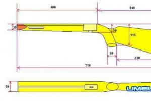
The single-sided tenoning machine for the production of straight and wedge tenons ShPK-40 is designed for processing tenons at one end of the workpiece and can be used in carpentry, construction, furniture and other woodworking industries. The machine allows processing workpieces up to 400 mm wide when forming straight box dowels and up to 110 mm wide when making wedge dowels. It is possible to process simultaneously several blanks (package) with a total thickness of not more than 100 mm. The length of the blanks must be at least 250 mm. The greatest length of the developed straight spikes is 50 mm, wedge - 10 mm.
A horizontal milling shaft, a lifting table and a hydraulic unit are mounted on a box-shaped frame.
The milling shaft is made in the form of a spindle with replaceable sets of cutters mounted on it. The spindle is mounted on two supports. The right support is provided by two angular contact bearings. The left removable bearing is a radial spherical ball bearing with a hub that includes the end of the spindle. The removable support arm can be tilted 90°, freeing up an area for changing the tool at the end.
The spindle is driven by an electric motor, which is mounted on a turntable so that the tension of the toothed transmission belt can be adjusted. Table 5 moves along the frame guides in the vertical direction by a hydraulic cylinder.
The workpiece is installed on the table and based on the lateral left or right guide ruler and the front end stop. The side rails are adjustable and allow you to customize the size of the outer eyelet.
The end stop can be adjusted in the range of 0…50 mm to provide the required tenon length. Fix the workpiece on the table with hydraulic clamps. A casing is installed in the upper part of the machine for removing chips, which is connected to the exhauster network. On the left side of the frame there is a hydraulic panel, on which hydraulic distributors, a safety valve and a throttle 3 are mounted to change the speed of the table.
The hydraulic drive of the machine provides reciprocating movement of the table through the cycle: clamping the workpiece, working stroke of the table with clamped workpieces down at a given feed rate, idling of the table with clamped workpieces up at an increased constant speed, unfastening the workpiece.
The hydrokinematic scheme of the machine is shown in fig. 114. With the electric motor of the hydraulic unit turned on, the oil from the vane pump NP through the strainer F and the distributors P1 and P2 enters the hydraulic tank B of the machine.
In the initial (upper) position, the table is held by oil pressure on the piston of the C1 cylinder. The oil outlet from the hydraulic cylinders C1 and C2 is locked in the middle position of the hydraulic distributors P1 and P2. With the simultaneous activation of the electromagnets and the distributors Pi and P2, the table and clamps occupy their original upper position.

Rice. 1. Tenoning machine for box straight dowels 111PK-40: 1 - bed, 2 - hydraulic unit, 3 - throttle, 4 - milling shaft, 5 - table, 6 - guide ruler, 7 - end stop, 8 - hydraulic clamp, 9 - workpiece , 10 - electric motor, 11 - hydraulic cylinder
The working stroke of the table is carried out by turning on the electromagnet b of the distributor P2. In this case, the electromagnets and distributors P1 and P2 are turned off - the workpieces are pressed. The pressure in the system rises, the pressure switch RD is activated and the solenoid b of the distributor P1 is turned on - the table is working.
At the end of the working stroke, the table presses the pin of the limit switch, which turns off the electromagnet b of the distributor P1 and simultaneously turns on the electromagnet a of the same distributor. The table begins to move up when the electromagnet b of the distributor P2 is turned on.
When the upper position of the table is reached, the limit switch is activated, which turns off the solenoid b of the hydraulic distributor P2 and turns on the electromagnet a of the hydraulic distributor P2. There is a departure of the clamps, and the workpiece is released. The table is fixed in the upper position, since the oil in the C1 cylinder is locked by the middle position of the P1 hydraulic distributor spool.
In the event of an emergency power outage, the table and clamps are fixed (the table stops, the workpiece is pressed), since the hydraulic valves P1 and P2 are automatically set to the middle position. To remove the workpiece from the cutting zone and detach it, it is necessary to raise the table to its original position by turning on the electromagnet a of the P1 hydraulic distributor and the electromagnet b of the P2 hydraulic distributor.
The cycle is switched on by pressing the "Cycle" button located on the control panel. In the "Setup" mode, you can move the table up and down with a stop in these positions.
The pressure in the system is regulated by the KP safety valve and controlled by the MN pressure gauge. The speed of the working stroke of the table is regulated by the throttle of the flow regulator RP.
Selecting the operating mode. The feed rate in the machine is assigned depending on the type of wood, the width of the workpiece and the length of the tenon. In table. 6 shows the cutting conditions when processing straight box spikes 8 mm wide at a wood moisture content of 10%.
When assigning modes, a short-term overload of the milling shaft electric motor is allowed no more than 25%. When processing wedge spikes of hardwood parts, the feed rate should be no more than 4.5 m / min.

Rice. Fig. 2. Hydrokinematic diagram of a tenoning machine for box straight tenons: a, b - electromagnets, B - tank, NP - vane pump, F - filter, KP - safety valve, MN - pressure gauge, RP - flow regulator, PI, P2 - distributors, RD - pressure switch, Ts1, Ts2 - hydraulic cylinders, XX - idling, PX - working stroke
Setting up machines. For processing straight box spikes, a set of 25 cutters is used. The set, fixed on the milling shaft, must have cutters of the same diameter, width B, equal to the width of the eye being produced. The deviation of the width of the fr-ez is allowed no more than 0.03 mm.
When processing wedge spikes, a set of two milling cutters with wedge teeth is used. The cutter teeth must have the same height and identical shape. It is not allowed to install cutters with chipped or blunt teeth on the spindle. The cutters on the quills must be securely fastened with nuts.
Before changing the cutting tool, you must set the switch on the control panel to the “Setup” position. This eliminates the possibility of turning on the milling shaft drive motor.
To replace the tool, unscrew the special nut of the support bracket, move it along the spindle and turn it 90°, providing free access to the tool from the end of the spindle. The new tool is installed in the following order. The side hinged bolts connecting the clamp to the table are moved to the upper position and securely fastened to the upper casing. By pressing the “Start table down” button, the table is set to its lowest position, after which the casing with clamps is tilted 90 °, providing free access to the tool. holding the spindle wrench, unscrew the left nut for fastening the set of cutters.
A set of cutters for a straight box tenon consists of two quills connected to each other by a gear coupling. First, the left quill with 12 cutters is removed, and then the right one with 13 cutters.
When changing tools, the safety rules must be observed. A set of cutters is removed and placed in a special box for its subsequent transportation to the grinding department of the workshop.
Both cutters for processing wedge spikes are installed in extreme positions relative to the spindle and side guide rulers through spacer rings and a bushing. After installing the tool, fix the folding bracket with a special nut. The bracket is equipped with a lock that prevents the drive motor from being turned on, so you should pay attention to the correct interaction of the bracket with the blocking microswitch.
The table is returned to its original upper position by pressing the "Start table up" button. Then set the clamp to the working position. The side guides of the ruler are adjusted depending on the width of the outer eye. The left and right rulers are adjusted so that two paired workpieces with straight spikes can be processed simultaneously. Adjustment of each line on required size from the extreme spike is carried out by the corresponding screw.
The end stop to the required tenon length is adjusted by turning the screw, followed by fixing it with a lock nut.
Hydraulic clamps are fixed on the table with two racks and hinged screws.
The value of the table stroke is determined by the position of the microswitches installed on the frame. To check the correctness of their work, the machine is switched to the “Setting” mode by the mode switch and the movement of the table up and down is practiced.
Rotate the throttle knob to set the desired speed of the stroke. Before starting the machine, an exhauster system for removing chips is turned on.
To improve the quality of milling spikes and prevent chipping when the cutters come out of the wood, an additional support is used - a backing bar or a shield on which the workpiece is installed. During the first pass, spikes are formed at the end of the backing board. The end of the backing board, which constantly interacts with the cutters, wears out quickly, so it should be periodically rearranged or replaced with a new one.
Work on machines. Starting the machine in an automatic cycle is carried out by alternately pressing the buttons for turning on the milling shaft electric motor and the hydraulic pump. The machine is operated by one worker. He takes a pack of boards, puts it on the table and aligns it, pressing it against the guide ruler and the front end stop. After pressing the “Cycle” button, the boards are pressed against the table by an automatically operating clamp, and the table makes a working and reverse move. In the original position of the part. are detached and the machinist, turning them 180°, again bases them in the dowel machine at the other end with the same machine setting. After the second pass, the finished parts are stacked.
Having finished processing a batch of parts, the machine operator proceeds to studding the mating boards, having previously moved the side guide ruler to the thickness of the spike or using the second guide ruler for this.
To avoid marriage, the boards entering the machine should not have wingedness, curvature, non-perpendicularity of the ends to the edges and face. During processing, the quality of the resulting studs is controlled with a tool or visually by trial assembly of the stud joint of paired parts.
The thickness of the stud and the width of the lug are measured with a caliper or other measuring instrument at points located at a distance of 1/4 of the stud length from the bottom of the lug and the end face of the stud. Check all the spikes and lugs of this part.
24.05.2015
Tenoning machines for straight tenon, according to the classification, are divided into one-sided and two-sided. On one-sided machines, in one working cycle, the studs are milled at one end of the workpiece, and on the two-sided, the studs are milled simultaneously at both ends of the workpiece.
Milling of straight spikes in both cases is carried out with a set of disk cutters or a set of cutters in the form of hooks. When using these cutters, the feed of the workpiece to the cutting tool can be carried out in the radial (along the radius of the cutter) or tangential (tangential to the cutting circle) direction.
The technological scheme for processing the spike (Fig. 147) shows that with a radial feed, the bottom of the cavity of the lug is concave with a radius of curvature r and an arrow of curvature
In practice, y does not exceed 1 mm and the concavity does not affect the assembly technology. In this case, one-sided machines with manual feed are used, on which only one workpiece can be processed at a time.
With a tangential feed of the workpiece, the bottom of the cavity is rectilinear (see Fig. 147). In this case, it is possible to mill blanks in batches from one and both ends at the same time. With a radial feed of the workpiece, the movement is intermittent, and with a tangential feed, it is continuous. The kinematics of chip formation is also different.
At present, tenoning machines with radial feed are not available. Previously produced ShP-1 machines are now used only in auxiliary production.
Tangential feed machines are widely used. The Moscow plant of woodworking machines and automatic lines mass-produces a single-sided tenoning machine ShPA-40 (Fig. 148, a). The main components of the machine are: a cast-iron bed 1, on which a horizontal milling shaft 2 is mounted, driven by an electric motor 6 through a V-belt and a cast-iron movable table 5 with two hydraulic membrane clamps 7 for fixing workpieces during their milling. The bed has vertical guides for the table.
The lower part of the table is rigidly attached to the rod of the hydraulic cylinder 4, which raises the table vertically relative to the milling shaft. On the upper plane of the table, a movable ruler 8 is fixed, to which the workpieces are pressed. The ruler on the table is installed perpendicular to the axis of the milling shaft, and along the axis it can move when adjusted to the desired width of the shoulder of the first tenon.
Clamps are placed on a horizontal crossbar, which is attached to the table through racks. This design allows them to move in horizontal and vertical planes and be set depending on the width and thickness of the workpiece being processed. Workplace clamp is fixed with special clamping devices. A guard 3 is installed on the milling shaft. It is mounted on three bearings, of which the third is a terminal, removable one. This allows you to install disc cutters on horizontal shaft.
On fig. 148, 6 shows the hydraulic circuit of the machine. Oil from tank 1 through filter 2 is supplied by pump 3 to the pressure line. The pressure line is connected by oil pipelines to the hydraulic cylinders of the clamps 11, the control valve 5, the reversing valve 5 and the safety valve 4. At the moment the carriage is loaded with workpieces, there is no oil pressure in the pressure line, since the upper cavity of the safety valve is connected to the drain valve through the unloading valve 9 and the control valve 8. highway.
The table is fed by turning the handle of the control valve 8 clockwise. This way, the upper cavity of the spool 5 and the spool 9 is connected to the pressure line, and the lower cavity of the spool 5 is connected to the drain. In the pressure line
the pressure rises to the value set on the valve 4, the pressure value is shown by the pressure gauge 10. At this time, the clamping cylinders 11 are activated, and the clamps are fixed on the workpiece table. At the same time, the spool piston 5 lowers under the action of oil pressure, connecting the lower cavity of the hydraulic cylinder 12 with the pressure line, and the upper cavity with the drain line. The rod of the hydraulic cylinder together with the table and the fixed workpieces rises up into the cutting zone of the cutters. In the extreme upper position of the table, the rod 13 attached to the table turns the control valve 8 to its original position. After the corresponding movement of the spool pistons, the oil from the line enters the upper cavity of the hydraulic cylinder 12, and the table begins to move down. The safety valve at this time maintains pressure, since in the unloading spool 9, under the action of a spring, the piston is in the upper position, and the tube connecting the safety valve to this spool is insulated. When the table takes the lower initial position, the rod 13 acts on the piston of the spool 9, and it moves to the extreme position, at which it connects the safety valve to the drain line. The pressure in the network drops, the pistons of the clamping hydraulic cylinders rise under the action of the springs, releasing the workpiece from clamping, and the cycle repeats. The feed rate is controlled by the throttle 5 and 7, and the idle speed does not change.
The domestic industry also produces double-sided tenoning box machines Sh2PA and Sh2PA-2. The latest model is a variation or modification of the Sh2PA machine. It differs only in an elongated bed, which allows you to process longer workpieces. This machine is the most modern, through-type, equipped with a conveyor feed mechanism and magazine loading, it is highly productive and can be used in the mass production of box parts and built into automatic lines.
The design of this machine provides for the basing of blanks on guide traverses only with a wide face. Spiking is performed with the vertical movement of the milling spindles from top to bottom, the workpiece stopped and the conveyor moving continuously.
On fig. 149 shown technology system machine Sh2PA. The workpiece 1 from the store 2 pushers 6 (conveyor chains 4) moves along the base beams 3. In the process of processing with saw blades 7, the workpieces are continuously pressed against the base planes by a conveyor clamp 5. The conveyor chain is equipped with hinged pushers 6. To turn on and off the pushers serve as guide lines 9, on which the pushers 6 rely on the shank and slide along them when the chains move. After the shank leaves the guide, the pusher overturns, leaving the workpiece 8 alone. When the workpiece is stationary, the caliper 10 with a set of cutters 11 moves vertically along the guides 12. In the process of lowering the milling tool, milling of the spikes occurs. The working and idle movement of the caliper 10 is transmitted from the drive shaft 13 by a helical gear 14.
The kinematic diagram of the Sh2PA-2 machine is shown in fig. 150. The conveyor feed mechanism is driven by an electric motor 1 through cylindrical gears and a worm gear 2. The vertical movement of the milling calipers is carried out using lever mechanisms 3 associated with cylindrical cams 4. Cams 4 along the generatrix of the cylinder have a profile groove into which the lever finger enters systems. The profile groove of the cam is made in such a way that, together with the levers, it copies the movement of the caliper up and down.
The profiled cam is driven by the main drive shaft by the chain conveyor 4a.
The milling head returns to its initial (upper) position with the same cam and two extension springs 5, mounted on the head support.
The calipers are equipped with chip collectors, which are connected to the pneumatic conveying system. To press the workpieces to the conveyor guides, clamping devices 13 and 11 (right and left), located above the conveyor chains 17, are used. The clamping device moves in horizontal and vertical directions using the handle 12. The clamping traverse is equipped with freely fitted rollers 9 with two grooves for V-belts . The saw spindle 10 is an MD motor, at the end of which a saw is fixed. The calipers of these spindles are equipped with mechanisms for vertical 20 and horizontal 21 movement. The spindle is set according to the graduated scale.
Milling spindle 6 is a horizontal shaft mounted on three ball bearings to the caliper, which moves along the vertical guides of the pedestal.
The drive of the milling caliper is from the electric motor 7 through the V-belt transmission 8. The electric motor is mounted on a swinging under-engine plate. From the store 22, the workpieces are captured by the stops 16 of the conveyor chains 17 and fed to the cutting heads.
Saw supports 19 are installed first along the way, forming the workpiece exactly along the length. Then the workpiece is fed into the zone of action of the milling spindles 6.
In the milling zone, the workpiece stops, as the pushing cam 16 of the chain comes off the guide 23 and rotates around the hinge axis, leaving the zone of engagement with the workpiece. At this moment, the milling spindles are lowered and the spikes are cut, then the spindles are raised to their original position and at this moment another workpiece comes up, pushes out the processed one, and itself stops in the cutting zone. Then the cycle repeats. The place where the workpiece stops in the milling zone is regulated by mechanism 18.
The movable pedestal (right) moves along the frame from an electric motor 14 with a power of 0.5 kW, through a single-thread worm gear 15 and a spur gear connected to a rack 23, mounted on the side wall of the machine frame. Precise installation of the right pedestal and cutting tools along the length of the part is carried out by handle 24, brought out to the front of the machine; the handle shaft is connected to the gear worm through a friction clutch.