DVB-T2 digital television antenna. Calculation of a wire antenna for t2. Do-it-yourself simple UHF antenna Do-it-yourself amplifier for Kharchenko antenna
This design got its name from the name of the discoverer engineer Kharchenko. Structurally, the antenna consists of two squares connected at one of their vertices by disconnected sides. Power is supplied at the connection points of the squares, while the input impedance of the antenna is close to 50 ohms. This antenna has a huge bandwidth compared to its constituent elements - squares. To date, there are a huge number of options for the Kharchenko antenna, in which instead of squares, circles, triangles, etc. are used to compile its canvas. Previously, the Kharchenko antenna was used to work in TV and VHF bands, but today it is mainly made to amplify WI-FI, 3G and 4G signals.
This homemade design will easily cover the entire frequency range of modern digital television in the range from 470 to 900 MHz. At the same time, her parameters are simply amazing, and even a novice radio amateur can handle the coordination.
Homemade design consists of two squares. Both stand at the corners and connect at one corner. In the case of horizontal polarization, the figure eight stands upright, and with vertical polarization, it lies on its side.
The side of the square is determined by the formula, as the wavelength ( λ ) divided by four.

We bring the power cable to the points of convergence of the sides of the squares.
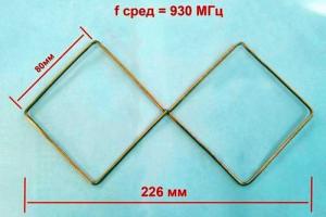
We make the "eight" from a monolithic copper wire with a cross section of 4 mm 2. Using pliers, bend the wire as shown in the figure below. We solder the ends together.
Border="0">
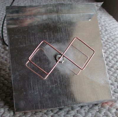
Then we need an aluminum plate 2 mm thick and 140 x 140 mm in size. She will act as a reflector. In the center of the plate, you need to drill a hole for the cable. Next, you need to fix the antenna in the center of the reflector at a distance of 3.6 centimeters, while the reflector with the antenna should not come into contact.

Having drilled holes for the clamps in the aluminum plate, I put the structure on the bracket from the satellite dish. Then I solder the cable, after passing it through the hole in the reflector.

Because the impedance of the antenna is 50 ohms, so a cable was used for this value. In addition, the conductor in such a cable turned out to be completely made of copper and it is very easy to solder it to the structure.
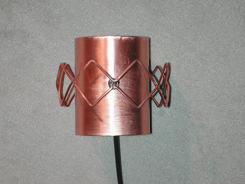
After the antenna is assembled, at the other end of the cable that will be connected to the modem, it is necessary to assemble a matching device for the 4G modem. To do this, we need some copper foil from which is used for. See the assembly sequence in the photos below:

If there is a connector for an external antenna, then the cable can be connected to it through an adapter. Setting up the 4G antenna is carried out experimentally, it can be rotated along the axis of the bracket until we get a clear signal. We judge the quality of the signal by the number of “sticks” in the program connection interface.
We touched upon the designs of a directional Wi-Fi antenna earlier. Bisquare, canned homemade rarities. People with enviable constancy are looking for a chance to get a better design. It was mentioned: instead of a traditional wire, it is better to take a PV1 wire of a similar section, which protects the installed antenna from bad weather. A board with double-sided foil, which is often recommended to be used as a reflector, does not tolerate bad weather very well, is not protected by anything, it is problematic to provide the design with a special case. The wind load on the product will increase. Today's review is devoted to methods for improving the design. Do-it-yourself Wi-Fi antenna for any bad weather!
Important! Try using shrink wrap for protection. Put on a reflector "fur coat", blow with a hairdryer. Soon the textolite will be tightly covered with a polymer film.
Bi-square Wi-Fi Antennas
The Wi-Fi antenna, built according to the biquad scheme, is formed by a grounded reflector, a figure-eight emitter with right (90 degrees) angles. It turns out something resembling trendy glasses with a thin bridge in the middle. The lower half is planted on the ground, the upper half - on the signal core of the cable RK - 50.
True, the antenna for Wi-Fi will be smaller in size. The side of the square along the midline of the copper core of the emitter is 30.5 mm. So, the figure eight is 1.5 (half the length of the side of the square) cm from the reflector and is parallel to the plate. In our case, the getinax fee is bad because it is difficult to get. A reflector is simply a sheet of electrically conductive metal. Tin, steel, aluminum will fit. Given the size of the emitter, you can make a WiFi antenna reflector using a 5.25 inch laser CD.
Biquadrat Kharchenko
The internal reflective aluminum layer is designed so that the laser beam does not lose energy on the surface. In addition, there is a hole in the center for the N-connector. It remains to open the protective plastic shell, put the reflective layer on the screen of the PK-50 cable. Please note: if the N-connector is not 1.5 cm away from the reflector with the emitter, the reception conditions will worsen. It is necessary to achieve the indicated position by placing thin metal washers or in place.
We remind you: the bi-square figure eight bends from the middle by turning 90 degrees. Both ends of the PV1 1x2.5 cable will return to the point. The thickness of the wire is 1.6 mm in diameter, between the centers of the core, the side of the square is 30.5 mm. The ends sit on the connector screen, are combined with a reflector (CD), the middle part will serve as a signal pickup. The radiation pattern of the device is sharply narrowed, equipped with one main lobe, which we direct to the signal source. If the case is in a room, you will have to experimentally find a reflected beam located in almost any direction.
The reflector will protect against neighboring interference, increase power. Blocks the multipath effect, which is of little use to the equipment. A homemade Wi-Fi antenna only accepts from a narrow sector. Thanks to this, we will connect the houses opposite by a network, which would not be possible with the supplied access point.
Please note: in other cases, there may not be an input connector on the case for connecting an antenna. Such access points are equipped with built-in metal circuits that receive radio waves. Traditionally, they look like intricate flat figures on the inside of the case. We'll have to unsolder the built-in antenna.
A capacitor can stand nearby, the capacitance serves the purpose of compensating for the compression ratio of the circuit. The built-in antenna is small, powerless to form a full-fledged device for receiving radio waves. The defect is neutralized by a tuning capacitor.
The element is not needed, because a full-sized antenna for a Wi-Fi router does not need to be compensated. Tear the homemade switching circuits above the capacitor. Do not use a typical 100W soldering iron when doing the installation. It will burn the electronic components of the board. You will need a small soldering iron equipped with a 25W needle tip.
The weight of the CD is small, the wind load is low, in contrast to the bulky design and will not kill anyone from below with a falling getinax board. It is recommended to avoid placing products in the sun, but in our case, the recorded information does not play a great role. If desired, seal the N-connector, extending the life of the solder joint. A special gel compound is used for mounting printed circuit boards. Similar ones are produced by the Allur company (St. Petersburg). A few words will explain how to make a Wi-Fi antenna more powerful with your own hands.
Bisquare antennas
Prologue: 2 weeks, I couldn’t find the reason for it, then I turned the antennas into a vertical one and got 20 Mbit per 5 km, instead of horizontal 4.
Vampirenysh, member of the forum Local Networks of Ukraine (spelling copied).
Before you buy a Wi-Fi antenna, think about it: theory shows that emitters arranged in rows narrow the radiation pattern in a direction perpendicular to the line along which to line up the elements. Translated into Russian, it means: if our houses are separated by 100 meters, the width of the antenna viewing sector for implementing the Wi-Fi communication channel barely exceeds 15 degrees. Useful power will be directed to the window of a friend (it will only harm the inhabitants of the apartment!). To implement the circuit, use a dual biquad antenna. You can increase the speed if you give the same to a friend on DR!
How to make a Wi-Fi antenna so that it does not interfere with neighbors. You can protect yourself from uninvited guests by changing the channel, polarization. There are three ways to protect the channel with the antenna configuration:
- Frequency selection.
- Direction selection (beam narrowing).
- Choice of polarization.
Usually, when there is Wi-Fi provided by the provider, the values \u200b\u200bare set by the communication provider, the client has to obey, but if you have your own equipment, the situation is different. We can put the antenna on vertical polarization if the neighbors use horizontal polarization. Our equipment will stop seeing each other. Can be done unilaterally or negotiated. Antennas will be needed like a biquad, set aside.
Television operates on horizontal polarization, communications on vertical polarization. Just a tradition, it is convenient to keep the walkie-talkie pin perpendicular to the ground when you speak. In this context, it is beneficial to use vertical polarization, usually found in routers. We offer a simple rule:
- Position with a friend opposite the antenna on the windows in the same way. Spatial compatibility is provided, which is a subspecies of electromagnetic. Microwaves, telephones, a mountain of 2.4 GHz interference equipment have been released. Position the antennas equally, vertically, horizontally, tilted. Experimentally look for the position at which the speed is greatest.
The promised novelty: a design of four squares lined up in a row. The radiation pattern will become narrow in the direction perpendicular to the formation. Copper wire or solid wire with a cross section of 2.5 mm 2 50 cm long. We recommend taking it with a margin. If a standard biquad Wi-Fi antenna for a laptop is an in-phase array of two frames, in our case there are four frames.

Frame for dual biquad antenna
When the wave moves, the current in neighboring squares is directed oppositely along the contour. Due to this, the effect of the impact of the field is added up. Now we need to get four in-phase squares. Find the middle of the wire, make a 90 degree bend. We measure 30 mm, make bends on each side in the opposite direction. We retreat twice as much, again bend in the first direction. You get a large letter W. Another 30 mm - bend the edges down at 90 degrees. One half is ready.
We do the second in the image and likeness so that the ends return to the point of the initial bend. Please note that it is not in vain that we recommend using a wire with a PVC sheath - the two crosshairs in the figure are mutually isolated.
We cut off the excess wire so that the ends do not reach the first bend by two or three millimeters. A Wi-Fi antenna for a computer requires a reflector, a good piece of foil textolite or a standard flat sheet will do. We use the N-connector for the connection.
The emitter is separated from the reflector by 1.5 cm in area. We plant the ends on the ground, the middle - on the signal core (cable for Wi-Fi antenna RK - 50). To reinforce the edges of the figure, use a ceramic or plastic tube. For fixing, electrical insulation, use glue, sealant. The street version is recommended to find a plastic case. Take the distance between the homemade antenna and the receiver smaller.
The next meeting will discuss Wi-Fi radio.
Again my exit. I have to keep the clients busy with the technical part of the project while the manager is on the phone.
The best alternative to the "wave channel" antenna for your operating conditions is the "Kharchenko" antenna. Do not look that it is so simple, in fact, these are two antennas in one bottle, sorry in the reflector and this gives a gain of as much as three decibels. Durable, reliable, small-sized, non-killable design, easy to use. The not too sharp radiation pattern ensures good radio wave penetration over rough terrain even in bad weather, hence the mobility of the antenna, which does not require a high rise from the ground, which allows you to quickly put the equipment into action in the field. The wide operating range of the antenna makes it versatile. Preference should be given to horizontal polarization, since for a forest area there will be less losses in the passage of radio waves. (No, in vain I started talking about polarization, now I’ll probably fall asleep myself).
Photo 1 shows two Russian-made Kharchenko antennas. Large antenna narrowband - for the range of 433 MHz. The upper antenna is broadband - for the range of 900 - 1800 MHz.
 |
| Photo 2. Two-story double circle. |
Here I made a similar antenna from metal-plastic for a summer residence, so in bad weather only digital television reaches me, and the antenna itself stands under a soft roof transparent for radio waves so that they don’t jinx it and don’t ask unnecessary questions. Three multiplex packages, two sports channels, two cartoons to catch my breath from my grandchildren and all this in excellent quality, I don’t tell anyone about this, otherwise they will come to me in the rain to inspect football, where I will seat everyone.
It all started with the fact that I assembled a homemade transformable antenna "wave channel". It was just interesting to find out how, at the maximum receiving distances, its elements affect the signal quality in the decimeter range. In principle, the antenna suited me, but as a disadvantage it proved to be narrow-band, perfectly receiving digital packets of my region densely spaced in frequency, and the level of digital reception slightly increased in the absence of director elements. It was then that I had a desire to make a simple universal antenna for the entire decimeter range of television broadcasting, since all TV channels occupying the meter wavelength range have already been transferred to it in digital format.
 |
| Rice. 1. |
 |
| Fig.2. |
I had already begun to assemble a two-story “wave channel” antenna (Fig. 1) into two ranges, but having simplified everything beyond recognition, (Fig. 2) thus came to the antenna "Kharchenko". Another popular name is two-story double square or double zigzag. From a metal-plastic tube (metal-plastic for short), the antenna that I assembled looks more like a two-story double circle or a pair of eights. Say what you like, but from flexible aluminum tubes with a diameter of 16 mm, covered with plastic, circles are better than squares, and for radio waves this geometric figure is the most optimal.
It is better to remember the number 8, it is this position of the antenna that has horizontal polarization, that is, it coincides with the polarization of the antennas of television transmitters. Again - this figure is its amplification, expressed in decibels.
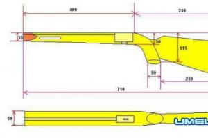
Antenna design.
Metal-plastic tube 2 meters long, 16 mm in diameter.
I divided the metal-plastic tube 2 meters long (cut off the metal-plastic when selling will be multiple meters) into four parts, each 0.5 meters long, and bent from circle segments. Thus, each circle has a length approximately equal to the wavelength. I flattened the ends of each tube, and cleaned the edges of the plastic, making holes in them for joint fastening.
Coaxial cableRG 59/U or RK 75- 3.7-35 m 7 meters long.
The distance is taken for the convenient location of the antenna in the attic, under a roof made of soft roof that is transparent to radio waves. The minimum cable length can be 1 - 1.5 meters, if the antenna is located near the TV. To reduce the reverse passage of high-frequency currents through the braid of the coaxial cable, I passed it through a hole in the tube at the point of zero potential. Zero potentials are the top and bottom of the eight, they are used to attach the supply loop to the reflector. To make an outdoor antenna, zero potential points must have electrical contact with a reflector, which is subsequently grounded to protect against lightning.
Reflector.
The reflector itself does not have to be made in the form of circles, as I did, in order to reduce the windage, that is, to reduce the swing of the pole from the wind in the case of using a remote structure. It can be made from a metal mesh, a sheet of metal, and if the antenna is used indoors, then from foil glued to plastic or cardboard. The edges of the reflector rings cleaned from plastic, I fastened with an aluminum plate.
Loop vibrator.
It consists of two tightened circles of metal-layer and having a common electrical contact. For desoldering the cable, a contact pad made of double-sided fiberglass 1 mm thick is used. The site ensures the rigidity of the structure, and in order to ensure a lower SWR value in the operating frequency range and better matching, it was necessary to reduce the gap between the rings in order to increase the capacitance between them. I had to make a double-sided cut of the print 1 mm wide with an offset.
It turned out that the pad for attaching the cable is a self-made capacitor, which provides better matching over the entire range from 490 to 900 MHz.
The distance between the eights or between the loop and the screen varies between 0.15 - 0.22 of the wavelength. This distance can be selected during the tuning process according to the signal level of the receiver. The distance in the fixing strips between the centers of the circles is 13 cm.
 |
| Rice. 5. Operating range of the antenna. |
The most interesting point is to check the operation of the antenna and compare it with existing designs and determine which antenna is better.
So which antenna should you choose?
To answer the question, I had to
another casting.
 |
| Photo 10. Antenna competition. |
At the same time, in the same place, I connected antennas with the same number of elements in turn and fixed the signal levels of three multiplex packets, choosing one channel in each, and then calculated the average values for each antenna. The antenna "Olympus 2014" and the two-story double circle differ from each other in terms of gain of 0.3 percent, I repeat 0.3 percent. Taking into account the measurement errors, I equalized the results and awarded first place for technicality to both antennas. In last place, a purchased antenna with an amplifier very similar to the Kharchenko antenna (the one in the center in photo 10) discredited itself greatly, because it did not work both in the city and at the maximum distance from it, receiving only one multiplex package with a hang .
 |
| Photo 11. First place. |
In terms of artistry, the first place is occupied by the Kharchenko antenna or a two-story double circle. It turned out to be more compact, that is, it takes up less space and it is convenient to hang it under a roof that is transparent to radio waves or attach it to a metal mast with a reflector.
Buy or not a decimeter antenna for watching digital TV? The question may seem strange, but on closer examination it becomes more reasonable. So, point by point:
- Where is the guarantee that the purchased antenna is worth the money spent on its purchase?
- When using a purchased decimeter television antenna in the country, you will most likely have to carry it back and forth with you in order to avoid theft.
- The need for such a device may arise spontaneously, somewhere on a picnic, and a trip to a special store is simply undesirable or impossible.
You can solve the problem with receiving the terrestrial television signal of the decimeter range using a home-made antenna for digital TV.
Types of dvb t2 antennas
Standard t2 dmv television - at the moment the newest mass used to transmit a digital signal. Its feature is a significant simplification of the receiving and transmitting devices through the use of decoding devices, the so-called tuners, some TV models already have a built-in digital signal decoding module. Significantly reduced signal power requirements, even a signal of low power is sufficient to reproduce a high quality picture, so there is almost always no need for an amplifier, it becomes unnecessary.
Antenna Kharchenko
Consider the device of a zigzag waveguide, the device of which was proposed by the enthusiast-engineer K. P. Kharchenko back in 1961 in the journal Radio. Outwardly, this device looks like a double rhombus or square adjacent to each other with open corners; at the junction points, the central core and the braid of the coaxial cable are connected.
To amplify the signal, you can use a metal reflector - a mirror that reflects a distant signal to the device. Digital Antenna Dimensions do-it-yourself depend on the wavelength of the received signal, it is clear that for the decimeter wavelength range and the dimensions of the dvb t2 antenna with your own hands will be within a few decimeters. The higher the reception frequency, the shorter the wave, the smaller the size. A room waveguide for receiving channels will have side dimensions of approximately 11 and 15 centimeters, overall external dimensions of 30 by 17 cm, and reflector dimensions of 50 by 50 cm.
For its manufacture, a little more than a meter of conductor is required - a copper or aluminum wire or tube with a diameter of 5-6 mm, preferably up to 10 mm or a strip, comparable width. The distance between the open points of the contact angles is 1–2 cm, the distance to the reflector is about 5–7 cm. This will be a long-range waveguide that allows you to receive 20 or more programs. The length of the television cable affects the operation of the antenna, if the cable is over 5-7 meters, you will need an amplifier, which one you choose.
- During operation, the waveguide should be deployed towards the nearest transmitting station; during the first installation, it is worth experimenting with the orientation of the device, achieving stable signal reception.
This type of antenna can also be successfully used to receive a weak signal from a cellular network, only the dimensions of the device will be several times smaller. There are enough online calculators on the network to calculate specific parameters for each case.
Travel antenna
To make this homemade product, in addition to a plug for connecting to a TV receiver, you only need two identical empty half liter metal cans from drinks. Instead of a coaxial cable, you can take the usual "noodles" for landlines. In the area of the neck of each empty and dry can, one “noodle” wire is fixed with a self-tapping screw, or a braid of a television cable is screwed to one, and its core to the other. The banks are located on one straight line, the reception is adjusted by changing the distance between them from 1 to 8 cm, as well as the exact orientation in the direction of the emitter. The device should not be placed too close to the TV.
 If you don’t want to bother with any needlework, and it’s a pity to spend extra money, then you can arrange a very simple device. But it will work steadily where the signal level is quite high. You will need to know the digital broadcast frequency in order to determine the wavelength. To do this, 300 is divided by the number of megahertz of the “numbers” broadcast frequency and a fairly accurate value in meters is obtained. For a frequency of 480 MHz, the wavelength will be 0.625 m, and for 700 MHz - approximately 0.430 m. When even the broadcast wavelength is reluctant to recognize, we simply take 0.63 m, the largest possible.
A piece of coaxial cable is taken equal to the calculated wavelength, the ends are stripped from the outer insulation so that there is access to the braid. The cut piece is bent into a broken circle - there should be a gap of 1-2 cm between the stripped ends and fixed in any way, as simple as possible, even on a cardboard box. On the first side, the central core of another piece of the same cable is soldered, on the other - a braid. A plug is attached to the end opposite the soldering point. Connect and enjoy watching digital broadcasting.
In order to independently make an antenna for dvb t2 with your own hands, it will not take much time and special costs, but the result will please.
Digital signals have been known to everyone for a long time. All TV organizations switched to the new format. Analog television devices stepped aside. But despite this, quite a few are in working order and can last more than one year. In order for outdated equipment to complete the allotted operational period, while there was the possibility of watching digital broadcasting, you will need to connect DVB-T to a television receiver and catch wave signals with a zigzag antenna.
For those who want to save the family budget and at the same time receive high-quality television broadcasting, you need to pay attention to the Kharchenko antenna for digital TV with your own hands.
This unique design has been known for a long time, but found itself relatively recently.
The principle of operation of the antenna for digital television
After radio communication appeared, the relevance of using the antenna device increased. Since the 60s of the twentieth century, at that time, the recognizable engineer Kharchenko flaunted a design of 2 rhombuses. Such a device allowed him to catch the air of the United States.
This is a double square of thick copper wire. The squares are connected by open corners to each other, in this place the cable from the TV is connected. To increase directivity, a grating made of a material capable of conducting current is mounted at the back.
The perimeter of the squares is equal to the wavelength to which the reception is tuned. About 12 mm should be the diameter of the wire for broadcasting from 1 to 5 TV channels. The design turns out to be far from compact, in the case of assembly for radio communication and TV of the meter range up to 12 channels.

To facilitate the device, a gasket with 3 wires of a smaller cross section was used. Despite this, the size and weight remained impressive.
The antenna in question received a second wind when broadcasting appeared in the UHF range. Most people know rhombuses, triangles and other home-made figures in the form of antenna devices for receiving a decimeter wave signal. Such an antenna plan was fun on balconies, windows of both private houses and multi-storey buildings.
At the beginning of the 2000s, American professor Trevor Marshall proposed using this design in Bluetooth and Wi-Fi networks.
The biquad antenna is also the antenna device of a Soviet engineer. This option is created according to the same principles as the usual biquadrate. A distinctive feature is that at the vertices of the squares, instead of the corners, there are additional squares.

As for the size of these squares, they are identical to the usual ones. This avoids additional calculations. It is enough to use the calculation of the standard biquadrate.
Recall that the wires in the place where they intersect require insulation from each other.
Necessary materials and tools
Do-it-yourself television antenna Kharchenko for DVB T2 is quite economical. In order to assemble the structure, you will need such details as:
- Wire;
- Coaxial cable;
- Wooden rail.
As for tools: pliers, hammer, sharp knife. If you plan to attach the antenna device to a wall or other surface, you will most likely need a drill to mount it.

Antenna calculation
Before proceeding with the creation of the structure, it will be necessary to calculate the Kharchenko antenna. This will allow you to assemble an effective device with maximum accuracy. The dimensions of the zigzag DVB T2 antenna play a significant role in increasing signal reception.
Since technology has stepped forward, there is now no need to leaf through reference books, look for formulas for calculating dimensions. And even more so to carry out complex mathematical calculations in order to correctly develop a sketch or a future drawing.
After that, you get information: about the required length of the copper wire, its sides, diameter.
Assembling the Kharchenko antenna for digital TV
Step-by-step instructions that will allow you to quickly assemble the Kharchenko antenna for digital television with your own hands:
- Determine the polarization and frequency of the wave. The device must be linear.
- The bi-square type of the antenna device in the form of a zigzag is made of copper. All elements are located at the corners, one of them touches. For horizontal type polarization, the figure eight must stand upright. If you do vertical polarization, then the design lies on its side.

- The side of the square is calculated using a special formula - the wavelength, which is divided by four.
- Imagine the design, it should be oval in shape, while being pulled in the center across the larger side. The sides do not touch, but are in close proximity to each other.
- We bring the antenna cable to the approach points on both sides. It will be necessary to block one direction of the diagram, for this a fetal screen made of copper is mounted, it will be located at a distance of 0.175 from the operating wavelength. It should be put on the cable sheath.

As for the reflector, it was previously made from textolite boards, which were coated with copper. Today, this component is made from metal plates. It is on this principle that the design for receiving digital television is made. Nothing complicated. Everything you need is at hand.
Antenna testing
The device has been created, it's time to check the effectiveness of the work done. To test the reception quality of the wave channel, you need to connect the antenna to the receiver. Turn on the TV and receiver.
Open the main menu of the set-top box, select automatic channel search. On average, this process will take only a few minutes. You can also find channels manually, but for this you will have to enter their frequency. To test Kharchenko's design for a TV, it is enough to simply evaluate the quality of the broadcast. If the channels show well, then the work is done correctly.

What if interference is visible? Rotate the TV antenna and see if the picture quality improves. When the optimal location is determined, simply fix the device. Naturally, it should be directed towards the TV tower.
Note.