Old two-wire wiring how to find the phase. How to find the phase with a multimeter: detailed instructions with step-by-step photographs for beginners with an explanation of typical mistakes of novice electricians. Multimeter. What is this device
To understand what a phase and zero are in an outlet, an ordinary person (not a specialist) does not need to delve into the electrical jungle. As an example, let's take an ordinary power outlet that receives alternating current.
Two electrical wires go to the outlet - zero and phase. The current flows only through one of them - the phase one (it is also called the working phase). The second wire is zero (or zero phase).

Zero and phase in old sockets
To connect the old outlet, use two conductors. One of them of blue color(working neutral conductor). This wire carries current from the power source to the appliance. If you take hold of a current-carrying wire, but do not touch the second wire, electric shock will not occur.
The second wire in the socket is phase. He happens to be the most different colors, including blue, green-yellow or light blue.
Note! Any voltage exceeding 50 volts is life-threatening.
Phase and zero in a modern outlet
There are three wires in modern type devices. Phase can be any color. In addition to phase and zero, there is one more wire (protective zero). The color of this conductor is green or yellow.

Voltage is applied through the phase. Zero is used for protective zeroing. The third wire is needed as additional protection - to take excess current during a short circuit. The current is redirected to ground or reverse side- to the source of electricity.
Note! Doesn't have practical value, phase and zero are located on the right or left. However, most often the phase is located on the left, and zero is on the right.
Determination of phase and zero with a multimeter or screwdriver
multimeter
The device is a combined electrical measuring device capable of performing several functions. The minimum equipment includes a voltmeter, an ohmmeter and an ammeter. Separate modifications are made in the form of current clamps. Both analog and electronic meters are available.

To start the measurement process, switch to AC voltage measurement mode. Measurement is carried out by one of several methods:
- We clamp one of the available probes with two fingers. We direct the second probe to the contact, which is located in the switch or socket. If the data on the monitor is insignificant (does not exceed 10 volts), we are talking about zero. If you touch another contact, the indicator will be higher - this is a phase.
- If there are concerns about the need to touch the probe, there is another way. We send one of the rods to the outlet. With the second rod we touch directly to the wall next to the outlet. The result will be approximately the same as in the case described above.
- There is a third way to measure with a multimeter. We touch the probe to a grounded surface (for example, the equipment case). Touch the surface to be measured with the second probe. If the wire is a phase, the multitester will detect 220 volts.
An indicator is a simple way to determine the phase, accessible even to a person who has taken up this business for the first time. The control screwdriver looks like a standard one. The difference is in the presence internal device at the indicator screwdriver. The screwdriver handle is made of special transparent plastic. Inside is a diode. The top part is made of metal.
Note! Do not use the indicator screwdriver for other purposes. It is not intended for unscrewing and tightening screws. Misuse of the control screwdriver will cause it to fail.

To find the phase and zero with a screwdriver, you need to perform the following sequence of operations:
- Touch the contact with the end of the screwdriver.
- Press your finger on the metal button at the top of the screwdriver.
- If the LED lights up, it is a phase. If he doesn't respond, it's zero.
Note! An indicator lamp rated for 220-380 volts will glow at voltages greater than 50 volts.
- Do not touch the lower end of the screwdriver while measuring.
- Keep the screwdriver clean, otherwise there is a risk of breaking the insulation.
- If you need to determine the absence of voltage, first check the performance of the device, which is definitely under voltage.
Advice! In a DC network, the polarity of the contacts is determined by a very in a simple way. To do this, simply lower the wires into a container of water. Bubbles will form near one of the wires - this is a minus. The second wire is positive.
Do not confuse an indicator screwdriver with a ringing device. The chime screwdriver is supplied with batteries. When working with such a device to determine zero and phase, you do not need to press the button, since the screwdriver will glow in any of the possible situations.
Modern indicator screwdrivers will relieve the headache of a person trying to figure out how to determine the phase, zero, ground. Difficulties noted below. For testing, a signal generated by a screwdriver is used. Of course, there are batteries inside. The old Soviet indicator screwdriver based on a single gas-discharge light bulb is unusable. Allows you to accurately determine the phase. Therefore, the other circuit is zero or ground.
Correctly determine the phase
Three-core wires
Let's start with terms. The Russian language is deprived of the word zero. But it was used in everyday life due to easy pronunciation. Zero is a distorted zero, ascending by roots to Latin. The programmer knows: the term NULL is used to mean empty, undefined variables (devoid of a type). Sometimes the type of data is convenient for compiling algorithms (when passing function values).
Now let's try to find the phase. A typical indicator screwdriver is formed by a steel probe, followed by a high-resistance resistance (for example, carbon), which limits the current, a small gas discharge lamp acts as a light source. Little things, but those who do not know the term contact button, are powerless to define zero. At the end of the indicator screwdriver handle there is a metal platform. This is a contact button that you bother to touch with your finger. Otherwise, the light bulb will refuse to glow when touching the phase.
Let's explain what's going on. The human body is endowed with capacity. Not so great, enough to pass a meager current. The phase begins to oscillate, the electrons go to the network and back. A small current is generated. The size is severely limited by the resistor, it is not easy to kill yourself by holding the contact pad of the indicator screwdriver with your hand, and the other by the water supply pipe. It is impossible to detect the ground directly with the instrument.
Phase detection is fundamental, no voltage should be applied to the chandelier socket when the switch is off. Otherwise, the usual process of changing a light bulb can become dangerous, the last. According to the regulations, the socket phase is on the left. If the switches are set as usual (turned on by pressing up), the methods for determining the phase degenerate by the ability to find left hand, understand where the bottom is:

Determining the position of the phase by the color of the insulation of the wire cores
The zero working wire is provided with blue insulation, the earth is yellow-green. Accordingly, the red (brown) color falls on the phase. The rule can be grossly violated. Houses of old buildings were often equipped with wires of two cores. The color of the insulation is in each case white. Individual devices, such as light or motion sensors, have a different layout. For example, the neutral wire is black. Here, get ready to look at the instruction manual, there are countless layout options.
Find a neutral wire in the apartment
According to the rules, the body of the access shield is grounded. It is carried out using a solid size terminal, tightened with a powerful bolt in houses of old construction, residents modern buildings easier to navigate the number of lived. Zero bus has the most big number connections, the phases are divided into apartments (good electricians hang stickers A, B, C; evil ones do not hang them). We can easily trace the layout of circuit breakers, counters.
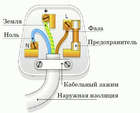
230 volt UK plug
In each case, the common wire will be zero. Color does not play a decisive role. Although according to the norms, modern cables are equipped with painted insulation. Please note - if the house is equipped with grounding, at least 5 lived at the entrance. The body of the shield is planted on yellow-green. The neutral wire will serve to drain the operating current from the devices (closes the circuit). Merging branches on the consumer side is not allowed. Here are three rules that help you figure out the access shield (note, according to the rules, the tenant should not show his nose there at all - they warned):
- The circuit breaker breaks the phase. There are two-pole models, they are used relatively rarely for rooms with special danger (bathroom). Therefore, by the position of the wire, it will be possible to say: this is a phase. Then it’s worth turning off the machine, ringing the vein on the side of the apartment. Definitely gives the position of the phase.
- The voltage between the neutral wire, any phase is 230 volts. Based on the key feature, we select a vein that gives the indicated difference to another. The spread between the phases is 400 volts. Percentage values are 10 higher, Russian chains are trying to meet European standards.
- With current clamps, we measure the values on the conductors. For each phase, a value will appear, the sum of which (by three) must flow back into the network through zero (or a suitable phase). Grounding is rarely used, the current here is close to zero with a uniform loading of the branches. The place where the value is the most is traditionally the null conductor.
- Ground terminal switchboard in sight. The sign will help to find the neutral wire in houses with NT-C-S. In other cases, grounding is supplied here.
Additional information about finding the ground, phase, neutral wire
We remind you that cases were considered when there is no indicator screwdriver at hand, but there are current clamps, a multimeter. Then, before entering the apartment, they find the ground, phase, neutral wire, the home network is called. There are three cores, the technique lies on the surface: between the phase and the other wire, the potential difference will be 230 volts. Please note that the technique is not suitable in other cases. For example, the voltage difference between two identical phase cores is round zero. It is difficult to measure and determine with a tester.
Let's add another way - the industry is prohibited. Bulb in a socket with two bare wires. Using a tool, they find a phase, it is possible to close the core to ground. Do not use water, gas, sewer pipes, other engineering structures. According to the rules, the braid of the cable antenna is equipped with grounding (grounding). Relative to it, it is permissible for a tester (a light bulb in a cartridge prohibited by standards) to find a phase.
For determined people, we recommend fire escapes, steel tires for lightning rods. It is necessary to clean the metal to a shine, call the phase site. Please note that not all fire escapes are grounded (although they must be), lightning rod tires are 100%. If you find such a flagrant arbitrariness, contact the governing organizations, if there is no reaction, inform the state authorities. Indicate violation of the rules of protective zeroing of buildings.
Modern screwdriver-indicators for determining the phase, neutral wire, earth
When it is impossible to understand what color the wires are, it is useful to use an indicator screwdriver. The instruction of the curiosity on batteries says: it will be possible to find the ground with the help of a probe. We hasten to disappoint readers - any long conductor is defined falsely. Phase broken in the area of plugs, neutral wire, real earth- the answer is one. Not every indicator screwdriver is able to perform the functions equally effectively. The meaning of the operation is as follows:

Screwdriver indicator
- An active indicator screwdriver is able to detect a long conductor by emitting a signal there, catching a response.
- In practice, if the quality of the contacts is poor, the wave quickly decays. An indicator screwdriver shows the presence of earth on an open phase plug.
- To determine the ground, there is a condition - you need to touch the contact pad with your finger. This is the difference between active and passive indicator screwdrivers. In the first one, it is possible to find the phase according to this principle, in the second, the correct determination occurs if there is no contact with this area.
A modern screwdriver-indicator at a distance will allow you to judge whether current flows through the wire. There is a special remote mode. Usually even two: increased and decreased sensitivity. Allows you to weed out the unused part of the wiring. Suppose there are known cases: builders brought two phases into the house instead of one, they confused them in places. Wiring must be used with great care.
I would like to note that in practice it is not easy to measure the resistance of the wiring. It is much more convenient to determine the presence of a phase. There is no danger of burning the Chinese tester (it happens at times when trying to measure the resistance of a live conductor). You should also be aware that low-resistance circuits are determined with an error. For example, most testers with a direct circuit of the probes do not give a zero scale. But if you can’t determine the ground using an active indicator screwdriver, bad contacts are easy. If, when the plugs are turned off, the light burns with a finger pressed to the contact pad, it's time to think about buying a new junction box machine, replace the twists with modern caps.
- Red - phase.
- Blue - neutral wire.
- Yellow is earth.
Usually water-soluble paint is washed off with difficulty. The colors of the electrical wires can be put down with the colors of the printers. The above system is not alone, often occurs. On sale we will find black color. You can use it however you like. Wire marking is done once and for all. It is easier to wash off the marking with concentrated acetic acid, the substance will be needed by those who intend to clean their hands (it is not always easy in practice). Finally, try not to stain your clothes.
When repairing electrical wiring, or maintaining it, it may often be necessary to determine which wire is connected to zero and which to phase. This is required for installing switches or switching other electrical equipment. Before telling how to determine zero and phase, let's talk about the prejudices associated with this.
The most common misconceptions
Here are the most common misconceptions associated with the definition of the neutral and phase wires:
An example of such equipment is a controller that controls the operation of gas boiler. When the error "not enough voltage" is indicated, the polarity must be reversed.
A similar problem can occur on the pulse generator, as well as when connecting laboratory measuring equipment;
- if there are three cores in the cable, and one of them is multi-colored, then it is grounding. One can never be sure of this, especially given the confusion with GOSTs in the last decade of the last century. Therefore, it is better to always check the cable.
Color coding
In order not to bother yourself with the search for zero and phase in the future, you must adhere to single standard prescribed in GOST R 50462-92.
The table shows what color this or that wire is indicated.
In older houses, wiring can be done with a single color wire. If you have a similar situation, we recommend marking the wiring leads with heat shrink tubing.
It is not necessary to trust the color coding if you have the slightest doubt. It is better to once again make sure that the purpose of the wires matches the colors.
The most accessible and common ways
The simplest way, which allows you to accurately determine the phase and neutral wires, is performed with an indicator screwdriver. You can buy it or build it yourself. The scheme of such a device is simple, it is shown in the figure below.
Designations on the diagram:
- A - contact plate;
- B - detector tip;
- R1 - resistance with a nominal value of 1.5 to 2 MΩ, power from 0.5 W;
- HG1 - any type of neon lamp.
Video instruction: determining the phase and zero with an indicator screwdriver
The compact dimensions of the parts used make it possible to assemble the device in the body of a ballpoint pen. Industrial designs are reminiscent appearance a small screwdriver.

Determining the connection of a wire to a phase or phase zero (in a two-wire electrical circuit) produced according to the step-by-step algorithm described below:
- the wiring is de-energized;
- the protective layer of insulation is removed from the wires to be tested (one centimeter will be enough);
- we turn on the electricity, since it will not work to determine zero if the phase is off;
- two wires are checked in turn with the tip of the probe, while touching the contact plate of the indicator, as shown in the photo;
- if the neon lamp lights up, the tested core is - phase electrical circuit.

In the socket, the voltage indicator works on two contacts
The situation when the probe detects two phases in the outlet and does not see zero can puzzle a novice electrician. The matter will be even more confused if you measure the potential difference with a multimeter or tester. They will show that there is no voltage. This characteristics zero break.
Note that with external signs of a lack of voltage in the wiring (according to the readings of the multimeter), you can get a fairly noticeable electric shock. That is why you can not neglect the voltage probe.
To solve this problem, it is enough to eliminate a break in the neutral wire, if you do not know how to do this, it is better to entrust this work to professional electricians.
Methods for three-core wiring
In this case, the third wire will be ground. The phase is easily found with a probe (how to do this was described above). To find zero and ground, you should use a multimeter or tester to determine them.
The procedure should be as follows:
- using a probe, we determine the phase;
- measure the voltage between the phase and the remaining two wires;
- the potential difference between zero and phase will be around 220V, the voltage between ground and phase will be less than this value.
Actually, having a multimeter, you can determine the ground, zero and phase without a voltage indicator. We will tell you how to do this using the M820D model.

For this purpose, it is necessary to set the measurement range of alternating current to more than 220V. The probes are connected to the V and COM jacks (shown in the photo below).

We alternately measure the voltage between the three wires, where it will be about 220V, one core is a phase, the second is zero. Accordingly, the third wire is ground.
Video: determining the phase and zero with an indicator screwdriver and a multimeter (2 ways)
No required appliances
IN household there must be at least a voltage probe, but if it is not there, do not be discouraged, there are ways to determine the ground, zero and phase without devices.
All that is required of you is to make a control lamp, approximately the same as shown in the photo. The lamp should work from 220V and be not too powerful (so as not to blind the eyes).

There are many options for implementing this device, the main thing is to ensure reliable insulation at the points of attachment of wires to the lamp and probes. Naturally, if you need to test the wires in the box on the ceiling, you need to make probes of the appropriate length.
To determine the phase, it is enough to connect one contact of such a probe to the wire under test, and the second to ground. The latter can be metal pipes heating or cold water. The place on the pipe that you will touch with the test lamp probe must first be cleaned.
The wire, when touched, the lamp will glow, and will be the phase.
A lot of videos have been published on the Internet on how to determine the phase without using any special equipment. For example, using raw potatoes or tap water. We want to warn that the repetition of such dubious experiments can cause significant damage to your health.
We have told how to determine zero and phase, and do it with maximum safety, so there is no need to invent new methods.
As you know, the electricity that is supplied to our house is three-phase. The voltage between any two outputs is 380 V. At the same time, we know that the voltage used in household appliances is 220 V. How is one converted to the other?
The neutral wire plays an important role here. If you measure the voltage between one of the phases and this wire, then it will just be equal to 220 V. In more modern sockets, an additional zero output is provided - this is the so-called protective zero.
A natural question arises as to what is the difference between the two mentioned zeros? The first of them, “working zero” (we are trying to determine it) is a neutral contact on a three-phase installation of a generating substation, connected to a neutral contact of a three-phase installation in a house or a separate entrance.
He may not be grounded at all. The main purpose is to create a closed electrical circuit when powered household appliances. In the second case, we are talking about. It is commonly referred to as "protective earth".
Due to the rather complex nature of alternating current, there are some typical views on the neutral wire and on the ground, which may not correspond to the real state of affairs:
- “There is no voltage at zero at all.” This is wrong. It is connected to the zero connector at the substation and is designed to create a potential difference at the output. Sometimes he is under pressure.
- “If there is grounding, then there will definitely not be a short circuit.” In most cases, it is. But if the current rises too quickly, it may not have time to leave through the ground in time.
- “If two cores in the cable are the same, and the third is different, then this is probably the ground.” It should be, but sometimes it isn't.
Methods for determining
 Digital multimeter
 Determination of zero and phase by using a multimeter. This device is very useful for working with electricity. It includes various features. It can be both an ammeter and a voltmeter or an ohmmeter.
Also, depending on the specific type, there may be other possibilities (for example, frequency measurement). These devices can be either analog or digital.
Using an indicator screwdriver. This screwdriver has a transparent handle. If you insert it into the outlet in a certain way, then when it hits the phase, the light will turn on.
There are several designs of such screwdrivers. In the simplest case, when testing, you need to touch the end of the pen. Without this, the flame will not light up.
With visual testing, the purpose of the wires can be determined by their colors.
Using a special phase. This is a small digital device that fits in the palm of your hand. One of the wires must be held in hand, the other is checked for phase.
Step by step instructions
Let's talk in more detail about how to produce such work.
When using a multimeter, you need to correctly set its operating range. It should be 220 V for AC voltage.
It can be used to solve two problems:
- Determine where the phase is, and where is the "working zero" or grounding.
- Determine where, in fact, grounding, and where is the zero output.
Let's talk about how to complete the first task first. Before starting, you need to correctly set the operating range of the device. Let's make it more than 220 V. Two probes are connected to the "COM" and "V" sockets.
We take the second of them and touch the outlet hole to be tested. If there is a phase, then a small voltage will be displayed on the multimeter. If the phase is not there, then zero voltage will be shown.
In the second case, the operating voltage should be 220V. We insert one wire where there is a phase. We test others with others. When it hits the ground, exactly 220 V will be shown, otherwise, the voltage will be slightly less.
Using a phase tester

We hold one wire neatly with our fingers, we use the other for testing. If we hit the phase in the outlet, then the numbers on the indicator will be much greater than zero. When hitting zero, the screen will also show zero or a small amount of voltage.
This device is convenient both because it is generally available on the radio measuring equipment market, and because the measurements are made with a sufficiently high accuracy.
Using an indicator screwdriver

It looks like an ordinary screwdriver, but with a slight difference. It has a transparent handle with a small light bulb inside. This, at first glance, a rather primitive device, is actually very convenient.
It is enough to simply insert it into the outlet hole, while touching the opposite end of the screwdriver with your finger. If there is a phase, then the light will light up. If there is a neutral wire or ground, then it will not burn. It is important to remember that it is strictly forbidden to touch the metal part of the screwdriver during the measurement process. This may result in electric shock.
In some cases, the phase and neutral wire can be determined without any instruments or fixtures. This can be done if you read the label correctly. This is not a reliable method, but in some cases it can be useful.
When working in modern houses, the rules for such labeling are generally followed.
So what are they:
- The wire where the phase is, usually brown or black in color.
- Null, It is customary to designate a wire that has a blue color.
- Green or yellow the wire that is used for grounding is indicated.
These rules may have been different in previous time periods. Also, they may change in the future. Therefore, the described method is suitable only for preliminary testing of the purpose of the wires.
How to distinguish between grounding and neutral wire when the phase is off?

Assume that there is no current in the network. Is there any difference in this case between ground and neutral wire? At first glance, it may seem that they are very similar to each other.
In fact, their functions are still different. Grounding is for emergencies. Through it, the electric charge goes to the ground. The neutral wire is part of the electrical circuit for powering household electrical appliances in the house.
Here, current, unlike grounding, is present. How can you tell them apart? With the phase off, you just need to measure the current between this wire and a known ground. If this is a neutral wire, then the current, although small, will be in this case. If there is grounding, then there can be no current here.
In what cases may be needed?
 With a huge variety of existing electrical appliances, there is a difference in what kind of electrical power they need. In different cases, such issues are resolved in different ways.
Sometimes, special devices are used for this - adapters. In some cases, it is only necessary to make the right connection to the outlet. In particular, when connecting an electric stove, there is a need to correctly determine when connecting where the phase is in the outlet, and where is the “working zero”.
In this, and in similar cases, it is impossible to do without such information.
Another situation where it is necessary is a different kind repair work. When conducting them, you need to know exactly which wire is energized (it must either be disconnected or securely insulated), and which one is not.
When connecting many household appliances, it really doesn’t matter which side the phase is on, but for the switch it may matter. Let's explain this. "Phase" should be fed to the switch, and "zero" let it be connected directly to the lamps in the chandelier.
At the same time, in the process of replacing the lamp in the chandelier, with the switch turned off, a person will not be shocked even if he accidentally touches it.
A digital multimeter is a very useful thing in everyday life. Using a tester, it is easy to determine which of the wires is phase, zero, and which is ground.
Any electrical network, both domestic and industrial, can be with direct current or with alternating current. With a constant supply of electrical voltage, the electrons move in one direction, with a variable supply, this direction constantly changes.
The variable network, in turn, consists of two parts - the working and empty phases. The working voltage, which is called “phase” in electricity, is supplied with a working voltage, but the empty one, which is called “zero”, is not. It is needed to create a closed network for operation and connection of electrical appliances, as well as for grounding the network.
Rules for using the multimeter
To determine the phase and zero using a multimeter, it is necessary to clean the ends of the wires from insulation, separate them in different directions to avoid contact, which will provoke a short circuit, and then apply electrical voltage.
On the multimeter, set the measuring limit of the alternating voltage above 220 V. Insert the voltage probe into the socket marked "V". Touch it to the cleaned core and follow the display. If the value is up to 20V - this is a phase wire, if there is no reading at all - this is zero.
For the correct use of the multimeter, the following rules must be observed:
- It is contraindicated to use the device in high humidity.
- Failed measuring probes must not be used.
- It is forbidden to measure parameters with a value exceeding the upper limit of the measuring instrument.
- During the measurement procedure, do not turn the switch and change the limits.
How a multimeter will help find the phase
In order for the multimeter to show which of the wires the phase is in, you need to set the mode on the device to determine the AC voltage, which is designated as V~, setting the measurement limit from 500 to 800 V. The probe is connected as standard, black to the “COM” connector, red to “VmA”.
How the multimeter shows zero
After the wire with the phase has been determined, it is easiest to find the zero one. By setting the red probe to the phase, touch other conductors, after which the tester should show a value of about 220 V. From this it will be clear that the second wire is either zero protective or zero working.
It is very difficult to determine with a multimeter where the zero protective wire is and where the zero worker is, since they duplicate each other. It is best to disconnect the input wire from the ground bus in the electrical panel, then there will not be 220 V between the phase and the ground wires in the tested room, as when checking the phase and zero.
We determine the device ground
The presence of a grounding contact does not mean that this contact is actually grounded. Quite often, this wire is not connected anywhere, but only creates visibility for the user. Competent electricians for the earth choose a wire with a strip, but if the master was inexperienced or neglected this task, then they might not remember the color marking. In such situations, voltage is best measured by touching water or heating pipes. On a wire with grounding, the voltage level will be less than on zero.
Other verification options
In addition to the listed methods for checking the phase and zero with a multimeter, there is a check using a control lama.
The method is quite unusual and requires special care, but effective.
Such a device requires a cartridge, a lamp, a wire with insulation cut off at the ends. When using a lamp, it will be possible to determine whether there is a phase or not, and which phase conductor cannot be established. If during the connection of the wiring of the test lamp to the conductors to be determined, it lights up, then one of the wires is phase, and the second is most likely zero. If it does not light up, then there is no phase, either phase or zero, which is also possible.
A screwdriver with an indicator to help us
The design of the tool is simple. A light bulb is built in. Sting on one end, shunt contact on the other.
The essence of checking with a control screwdriver is to perform the following actions:
- Turn off the power supply from the shield.
- Remove the insulation from the cores that need to be checked for 1 cm.
- We separate them in different directions to avoid contact.
- Apply voltage by turning on the introductory machine.
- Bring the tip of the screwdriver to the bare wiring.
- If the indicator window lights up during this action, then this is a phase, if it is absent, then it is zero.
- Tag desired core, turn off the automatic box and connect the switching device.
When working with a probe, everyone must follow the safety rules, which consist in the fact that when taking a measurement, you must not touch the screwdriver at the bottom. The tool must be kept clean. Before determining the absence of voltage (as opposed to its presence) in the outlet, you can check the device for serviceability using other electrical equipment that is energized.
By wire color
The simplest and most reliable way to determine the phase and zero is by the color of the wires.
But only if you are sure that the wiring is connected in accordance with all the rules!
Basically, she always lived with a phase of black, brown, white or gray, and zero is blue or blue. May also be lived Green colour or yellow-green, this indicates the presence of a conductor with grounding.
In this case, you can do without measuring instruments, according to the color, it is clear where the phase is, and where is zero.
When installing electrical wiring, the biggest threat is phase conductors. To prevent a situation that entails a fatal outcome - they are painted in screaming bright colors. This is done so that, under certain circumstances, an electrician from several wires can quickly select the most dangerous and treat them with care.