Measurement of thermal conductivity. Basic research. A.4 Temperature sensors
during their thermal motion. In liquids and solids - dielectrics - heat transfer is carried out by direct transfer of the thermal motion of molecules and atoms to neighboring particles of matter. In gaseous bodies, the propagation of heat by thermal conduction occurs due to the exchange of energy during the collision of molecules with different speeds of thermal motion. In metals, thermal conductivity is carried out mainly due to the movement of free electrons.
The main term of thermal conductivity includes a number of mathematical concepts, the definitions of which, it is advisable to recall and explain.
temperature field- these are sets of temperature values \u200b\u200bin all points of the body at a given moment in time. Mathematically, it is described as t = f(x, y, z, t). Distinguish stationary temperature field when the temperature at all points of the body does not depend on time (does not change over time), and non-stationary temperature field. In addition, if the temperature changes only along one or two spatial coordinates, then the temperature field is called, respectively, one- or two-dimensional.
Isothermal surface is the locus of points that have the same temperature.
temperature gradient — grad t there is a vector directed along the normal to the isothermal surface and numerically equal to the derivative of the temperature in this direction.
According to the basic law of heat conduction - the law Fourier(1822), the heat flux density vector transmitted by thermal conduction is proportional to the temperature gradient:
q = - λ grad t, (3)
Where λ - coefficient of thermal conductivity of the substance; its unit of measure Tue/(m K).
The minus sign in equation (3) indicates that the vector q directed opposite to the vector grad t, i.e. towards the lowest temperature.
heat flow δQ through an arbitrarily oriented elementary area dF is equal to the scalar product of the vector q to the elementary area vector dF, and the total heat flux Q across the entire surface F is determined by integrating this product over the surface F:
COEFFICIENT OF THERMAL CONDUCTIVITY
Coefficient of thermal conductivity λ in law Fourier(3) characterizes the ability of a given substance to conduct heat. The values of the thermal conductivity coefficients are given in reference books on the thermophysical properties of substances. Numerically, the thermal conductivity coefficient λ = q/ grad t equal to the heat flux density q with temperature gradient grad t = 1 K/m. The lightest gas, hydrogen, has the highest thermal conductivity. At room conditions thermal conductivity of hydrogen λ = 0,2 Tue/(m K). Heavier gases have less thermal conductivity - air λ = 0,025 Tue/(m K), in carbon dioxide λ = 0,02 Tue/(m K).
Pure silver and copper have the highest thermal conductivity: λ = 400 Tue/(m K). For carbon steels λ = 50 Tue/(m K). In liquids, the thermal conductivity is usually less than 1 Tue/(m K). Water is one of the best liquid conductors of heat, for it λ = 0,6 Tue/(m K).
The thermal conductivity coefficient of non-metallic solid materials is usually below 10 Tue/(m K).
Porous materials - cork, various fibrous fillers such as organic wool - have the lowest thermal conductivity coefficients λ <0,25 Tue/(m K), approaching at a low packing density to the coefficient of thermal conductivity of the air filling the pores.
Temperature, pressure, and, for porous materials, humidity can also have a significant impact on the thermal conductivity. Reference books always give the conditions under which the thermal conductivity of a given substance was determined, and for other conditions these data cannot be used. Value ranges λ for various materials are shown in fig. 1.

Fig.1. Intervals of values of thermal conductivity coefficients of various substances.
Heat transfer by thermal conduction
Homogeneous flat wall.
The simplest and very common problem solved by the theory of heat transfer is to determine the density of the heat flux transmitted through a flat wall with a thickness δ , on the surfaces of which temperatures are maintained tw1 And t w2 .(Fig. 2). The temperature changes only along the thickness of the plate - one coordinate X. Such problems are called one-dimensional, their solutions are the simplest, and in this course we will restrict ourselves to consideration of only one-dimensional problems.
Considering that for the one-numbered case:
grad t = dt/dх, (5)
and using the basic law of heat conduction (2), we obtain a differential equation for stationary heat conduction for a flat wall:
In stationary conditions, when energy is not spent on heating, the heat flux density q unchanged in wall thickness. In most practical problems, it is approximately assumed that the thermal conductivity coefficient λ does not depend on temperature and is the same throughout the entire thickness of the wall. Meaning λ found in reference books at a temperature of:
average between the temperatures of the wall surfaces. (The calculation error in this case is usually less than the error of the initial data and tabular values, and with a linear dependence of the thermal conductivity coefficient on temperature: λ = a + bt exact calculation formula for q does not differ from the approximate one). At λ = const:
![]() (7)
(7)
those. temperature dependence t from the coordinate X linear (Fig. 2).

Fig.2. Stationary temperature distribution over the thickness of a flat wall.
Dividing the variables in equation (7) and integrating over t from tw1 before tw2 and by X from 0 to δ :
![]() , (8)
, (8)
we obtain the dependence for calculating the heat flux density:
![]() , (9)
, (9)
or heat flow power (heat flow):
![]() (10)
(10)
Therefore, the amount of heat transferred through 1 m 2 walls, directly proportional to the coefficient of thermal conductivity λ and the temperature difference of the outer surfaces of the wall ( t w1 - t w2) and inversely proportional to the wall thickness δ . The total amount of heat through the wall area F also in proportion to this area.
The resulting simplest formula (10) is very widely used in thermal calculations. This formula not only calculates the heat flux density through flat walls, but also makes estimates for more complex cases, simplistically replacing walls of complex configuration with a flat wall in the calculations. Sometimes, already on the basis of an assessment, one or another option is rejected without further expenditure of time for its detailed study.
Body temperature at a point X is determined by the formula:
t x = t w1 - (t w1 - t w2) × (x × d)
Attitude λF/δ is called the thermal conductivity of the wall, and the reciprocal δ/λF thermal or thermal resistance of the wall and is denoted Rλ. Using the concept of thermal resistance, the formula for calculating the heat flux can be represented as:
Dependence (11) is similar to the law Ohma in electrical engineering (the strength of the electric current is equal to the potential difference divided by the electrical resistance of the conductor through which the current flows).
Very often, thermal resistance is called the value δ / λ, which is equal to the thermal resistance of a flat wall with an area of 1 m 2.
Calculation examples.
Example 1. Determine the heat flux through the concrete wall of a building with a thickness of 200 mm, height H = 2,5 m and length 2 m if the temperatures on its surfaces are: t с1\u003d 20 0 C, t с2\u003d - 10 0 С, and the coefficient of thermal conductivity λ =1 Tue/(m K):
![]() = 750 Tue.
= 750 Tue.
Example 2. Determine the thermal conductivity of the wall material with a thickness of 50 mm, if the heat flux density through it q = 100 Tue/m 2, and the temperature difference on the surfaces Δt = 20 0 C.
![]() Tue/(m K).
Tue/(m K).
Multilayer wall.
Formula (10) can also be used to calculate the heat flux through a wall consisting of several ( n) layers of dissimilar materials closely adjacent to each other (Fig. 3), for example, a cylinder head, gasket and cylinder block made of different materials, etc.

Fig.3. Temperature distribution over the thickness of a multilayer flat wall.
The thermal resistance of such a wall is equal to the sum of the thermal resistances of the individual layers:
 (12)
(12)
In formula (12), it is necessary to substitute the temperature difference at those points (surfaces), between which all the summed thermal resistances are “included”, i.e. in this case: tw1 And w(n+1):
 , (13)
Where i- layer number.
In the stationary mode, the specific heat flux through the multilayer wall is constant and the same for all layers. From (13) follows:
 . (14)
It follows from equation (14) that the total thermal resistance of a multilayer wall is equal to the sum of the resistances of each layer.
Formula (13) can be easily obtained by writing the temperature difference according to formula (10) for each of P layers of a multilayer wall and adding up all P expressions, taking into account the fact that in all layers Q has the same meaning. When added, all intermediate temperatures will decrease.
The temperature distribution within each layer is linear, however, in different layers, the slope of the temperature dependence is different, since according to formula (7) ( dt/dx)i = - q/λ i. The density of the heat flux passing through the entire layer is the same in the stationary mode, and the thermal conductivity of the layers is different, therefore, the temperature changes more sharply in layers with lower thermal conductivity. So, in the example in Fig. 4, the material of the second layer (for example, gaskets) has the lowest thermal conductivity, and the third layer has the highest.
Having calculated the heat flux through a multilayer wall, one can determine the temperature drop in each layer using relation (10) and find the temperatures at the boundaries of all layers. This is very important when using materials with a limited allowable temperature as heat insulators.
The temperature of the layers is determined by the following formula:
t sl1 \u003d t c t1 - q × (d 1 × l 1 -1)
t sl2 \u003d t c l1 - q × (d 2 × l 2 -1)
Contact thermal resistance. When deriving formulas for a multilayer wall, it was assumed that the layers closely adjoin each other, and due to good contact, the contacting surfaces of different layers have the same temperature. Ideally tight contact between the individual layers of a multilayer wall is obtained if one of the layers is applied to another layer in a liquid state or in the form of a fluid solution. Solid bodies touch each other only at the tops of the roughness profiles (Fig. 4).
The contact area of the vertices is negligible, and the entire heat flow goes through the air gap ( h). This creates additional (contact) thermal resistance. R to. Thermal contact resistances can be determined independently using the appropriate empirical dependencies or experimentally. For example, a gap thermal resistance of 0.03 mm approximately equivalent to the thermal resistance of a layer of steel with a thickness of about 30 mm.

Fig.4. Image of contacts of two rough surfaces.
Methods for reducing thermal contact resistance. The total thermal resistance of the contact is determined by the cleanliness of processing, the load, the thermal conductivity of the medium, the thermal conductivity coefficients of the materials of the contacting parts, and other factors.
The greatest efficiency in reducing thermal resistance is provided by the introduction into the contact zone of a medium with a thermal conductivity close to that of the metal.
There are the following possibilities for filling the contact zone with substances:
Use of gaskets made of soft metals;
Introduction to the contact zone of a powdered substance with good thermal conductivity;
Introduction to the zone of a viscous substance with good thermal conductivity;
Filling the space between the protrusions of roughness with liquid metal.
The best results were obtained when the contact zone was filled with molten tin. In this case, the thermal resistance of the contact practically becomes equal to zero.
Cylindrical wall.
Very often, coolants move through pipes (cylinders), and it is required to calculate the heat flux transmitted through the cylindrical wall of the pipe (cylinder). The problem of heat transfer through a cylindrical wall (with known and constant temperatures on the inner and outer surfaces) is also one-dimensional if considered in cylindrical coordinates (Fig. 4).
The temperature changes only along the radius, and along the length of the pipe l and along its perimeter remains unchanged.
In this case, the heat flow equation has the form:
 . (15)
Dependence (15) shows that the amount of heat transferred through the cylinder wall is directly proportional to the thermal conductivity coefficient λ , pipe length l and temperature difference ( t w1 - t w2) and inversely proportional to the natural logarithm of the ratio of the outer diameter of the cylinder d2 to its inner diameter d1.

Rice. 4. Change in temperature across the thickness of a single-layer cylindrical wall.
At λ = const temperature distribution by radius r of a single-layer cylindrical wall obeys a logarithmic law (Fig. 4).
Example. How many times are heat losses reduced through the wall of the building, if between two layers of bricks with a thickness of 250 mm install a foam pad 50 thick mm. The thermal conductivity coefficients are respectively equal: λ kirp . = 0,5 Tue/(m K); λ pen. . = 0,05 Tue/(m K).
To study the thermal conductivity of a substance, two groups of methods are used: stationary and non-stationary.
The theory of stationary methods is simpler and more fully developed. But non-stationary methods, in principle, in addition to the thermal conductivity coefficient, allow obtaining information about the thermal diffusivity and heat capacity. Therefore, much attention has recently been paid to the development of non-stationary methods for determining the thermophysical properties of substances.
Here, some stationary methods for determining the thermal conductivity of substances are considered.
A) Flat layer method. With a one-dimensional heat flow through a flat layer, the thermal conductivity coefficient is determined by the formula
Where d- thickness, T 1 and T 2 - temperatures of the "hot" and "cold" surface of the sample.
To study thermal conductivity by this method, it is necessary to create a heat flux close to one-dimensional.
Temperatures are usually measured not on the surface of the sample, but at some distance from them (see Fig. 2), therefore, it is necessary to introduce corrections into the measured temperature difference for the temperature drop in the heater and cooler layers, to minimize the thermal resistance of the contacts.
When studying liquids, to eliminate the phenomenon of convection, the temperature gradient must be directed along the gravitational field (down).

Rice. 2. Scheme of flat layer methods for measuring thermal conductivity.
1 – test sample; 2 - heater; 3 - refrigerator; 4, 5 - insulating rings; 6 – security heaters; 7 - thermocouples; 8, 9 - differential thermocouples.
b) Jaeger's method. The method is based on solving a one-dimensional heat equation describing the propagation of heat along a rod heated by an electric current. The difficulty of using this method lies in the impossibility of creating strict adiabatic conditions on the outer surface of the sample, which violates the one-dimensionality of the heat flux.
The calculation formula looks like:
 (14)
(14)
Where s- electrical conductivity of the test sample, U is the voltage drop between the extreme points at the ends of the rod, DT is the temperature difference between the middle of the rod and the point at the end of the rod.

Rice. 3. Scheme of the Jaeger method.
1 - electric furnace; 2 - sample; 3 - trunnions for fastening the sample; T 1 ¸ T 6 - thermocouple termination points.
This method is used in the study of electrically conductive materials.
V) Cylindrical layer method. The investigated liquid (bulk material fills a cylindrical layer formed by two coaxial cylinders. One of the cylinders, most often internal, is a heater (Fig. 4).

Fig. 4. Scheme of the cylindrical layer method
1 - inner cylinder; 2 - main heater; 3 - layer of the test substance; 4 - outer cylinder; 5 - thermocouples; 6 - security cylinders; 7 - additional heaters; 8 - body.
Let us consider in more detail the stationary process of heat conduction in a cylindrical wall, the temperature of the outer and inner surfaces of which is maintained constant and equal to T 1 and T 2 (in our case, this is the layer of the substance under study 5). Let us determine the heat flux through the wall under the condition that the inner diameter of the cylindrical wall is d 1 = 2r 1, and the outer diameter is d 2 = 2r 2 , l = const, and heat propagates only in the radial direction.
To solve the problem, we use equation (12). In cylindrical coordinates, when  ; equation (12), according to (10), takes vit:
 . (15)
Let's introduce the notation dT/dr= 0, we get
After integrating and potentiating this expression, passing to the original variables, we get:
![]() . (16)
. (16)
As can be seen from this equation, the dependence T=f(r) is logarithmic.
The integration constants C 1 and C 2 can be determined by substituting the boundary conditions into this equation:
at r \u003d r 1 T \u003d T 1 And T 1 \u003d C 1 ln r1+C2,
at r=r2 T=T2 And T 2 \u003d C 1 ln r2+C2.
The solution of these equations with respect to WITH 1 and From 2 gives:
 ;
; 
Substituting these expressions for From 1 And From 2 into equation (1b), we get
 (17)
(17)
heat flow through the area of a cylindrical surface of radius r and length is determined using the Fourier law (5)
 .
.
After substitution, we get
 . (18)
Thermal conductivity coefficient l at known values Q, T 1 , T 2 , d 1 , d 2 , calculated by the formula
 . (19)
To suppress convection (in the case of a liquid), the cylindrical layer must have a small thickness, typically fractions of a millimeter.
Reduction of end losses in the cylindrical layer method is achieved by increasing the ratio / d and security heaters.
G) hot wire method. In this method, the relation / d increases by decreasing d. The inner cylinder is replaced by a thin wire, which was both a heater and a resistance thermometer (Fig. 5). As a result of the relative simplicity of design and detailed development of the theory, the heated wire method has become one of the most advanced and accurate. In the practice of experimental studies of the thermal conductivity of liquids and gases, he occupies a leading place.

Rice. 5. Scheme of the measuring cell made according to the heated wire method. 1 - measuring wire, 2 - tube, 3 - test substance, 4 - current leads, 5 - potential taps, 6 - external thermometer.
Under the condition that the entire heat flux from section AB propagates radially and the temperature difference T 1 - T 2 is not large, so that l = const can be considered within these limits, the thermal conductivity of the substance is determined by the formula
 , (20)
Where Q AB = T×U AB is the power dissipated on the wire.
e) ball method. It finds application in the practice of studying the thermal conductivity of liquids and bulk materials. The substance under study is given the shape of a spherical layer, which makes it possible, in principle, to exclude uncontrolled heat losses. Technically, this method is rather complicated.
Physical methods of analysis are based on the use of some specific physical effect or a certain physical property of a substance. For gas analysis use density, viscosity, thermal conductivity, refractive index, magnetic susceptibility, diffusion, absorption, emission, absorption of electromagnetic radiation, as well as selective absorption, sound speed, reaction heat, electrical conductivity, etc. Some of these physical properties and phenomena make continuous gas analysis and allow to achieve high sensitivity and measurement accuracy. The choice of a physical quantity or phenomenon is very important to eliminate the influence of unmeasured components contained in the analyzed mixture. The use of specific properties or effects makes it possible to determine the concentration of the desired component in a multicomponent gas mixture. Nonspecific physical properties can be used, strictly speaking, only for the analysis of binary gas mixtures. Viscosity, refractive index and diffusion are of no practical importance in the analysis of gases.
The transfer of heat between two points with different temperatures occurs in three ways: convection, radiation and heat conduction. At convection heat transfer is associated with the transfer of matter (mass transfer); heat transfer radiation occurs without the participation of matter. Heat transfer thermal conductivity occurs with the participation of matter, but without mass transfer. The transfer of energy occurs due to the collision of molecules. Coefficient of thermal conductivity ( X) depends only on the type of substance transferring heat. It is a specific characteristic of a substance.
The dimension of thermal conductivity in the CGS system cal / (s cm K), in technical units - kcalDmch-K), in the international SI system - WDm-K). The ratio of these units is as follows: 1 cal / (cm s K) \u003d 360 kcal Dm h K) \u003d 418.68 W Dm-K).
The absolute thermal conductivity during the transition from solid to liquid and gaseous substances varies from X = 418.68 Wdm-K)] (thermal conductivity of the best heat conductor - silver) up to X order 10 _6 (thermal conductivity of the least conductive gases).
The thermal conductivity of gases increases strongly with increasing temperature. For some gases (GH 4: NH 3), the relative thermal conductivity increases sharply with increasing temperature, and for some (Ne) it decreases. According to the kinetic theory, the thermal conductivity of gases should not depend on pressure. However, various reasons lead to the fact that with increasing pressure, the thermal conductivity slightly increases. In the pressure range from atmospheric to several millibars, thermal conductivity does not depend on pressure, since the mean free path of molecules increases with a decrease in the number of molecules per unit volume. At a pressure of -20 mbar, the mean free path of the molecules corresponds to the size of the measuring chamber.
The measurement of thermal conductivity is the oldest physical method of gas analysis. It was described in 1840, in particular, in the works of A. Schleiermacher (1888-1889) and has been used in industry since 1928. In 1913 Siemens developed a hydrogen concentration meter for airships. Thereafter, for many decades, instruments based on the measurement of thermal conductivity were developed with great success and widely used in the rapidly growing chemical industry. Naturally, at first only binary gas mixtures were analyzed. The best results are obtained with a large difference in the thermal conductivity of the gases. Hydrogen has the highest thermal conductivity among gases. In practice, it was also justified to measure the concentration of CO s in flue gases, since the thermal conductivities of oxygen, nitrogen and carbon monoxide are very close to each other, which allows the mixture of these four components to be considered as quasi-binary.
The temperature coefficients of thermal conductivity of different gases are not the same, so you can find the temperature at which the thermal conductivities of different gases are the same (for example, 490 ° C - for carbon dioxide and oxygen, 70 ° C - for ammonia and air, 75 ° C - for carbon dioxide and argon) . When solving a certain analytical problem, these coincidences can be used by taking a ternary gas mixture for a quasi-binary one.
In gas analysis, we can assume that thermal conductivity is an additive property. By measuring the thermal conductivity of the mixture and knowing the thermal conductivity of the pure components of the binary mixture, one can calculate their concentrations. However, this simple relationship cannot be applied to any binary mixture. So, for example, mixtures of air - water vapor, air - ammonia, carbon monoxide - ammonia and air - acetylene at a certain ratio of components have a maximum thermal conductivity. Therefore, the applicability of the heat conduction method is limited to a certain range of concentrations. For many mixtures, there is a non-linear dependence of thermal conductivity and composition. Therefore, it is necessary to take a calibration curve, according to which the scale of the recording instrument should be made.
Thermal conductivity sensors(thermoconductometric sensors) consist of four small gas-filled chambers of small volume with thin platinum conductors of the same size and with the same electrical resistance placed in them isolated from the body. The same direct current of a stable value flows through the conductors and heats them. Conductors - heating elements - are surrounded by gas. Two chambers contain the measurement gas, the other two contain the reference gas. All heating elements are included in the Whiteton bridge, with which the measurement of a temperature difference of the order of 0.01°C is not difficult. Such a high sensitivity requires an exact equality of the temperatures of the measuring chambers, so the entire measuring system is placed in a thermostat or in the measuring diagonal of the bridge, and a resistance is included for temperature compensation. As long as the heat dissipation from the heating elements in the measurement and comparison chambers is the same, the bridge is in equilibrium. When gas with a different thermal conductivity is supplied to the measuring chambers, this equilibrium is disturbed, the temperature of the sensitive elements changes and, along with this, their resistance. The resulting current in the measuring diagonal is proportional to the concentration of the measured gas. To increase the sensitivity, the operating temperature of the sensitive elements should be increased, but care must be taken to maintain a sufficiently large difference in the thermal conductivity of the gas. So, for various gas mixtures, there is an optimal temperature in terms of thermal conductivity and sensitivity. Often the difference between the temperature of the sensitive elements and the temperature of the walls of the chambers is selected from 100 to 150°C.
Measuring cells of industrial thermal conductometric analyzers usually consist of a massive metal case in which measuring chambers are drilled. This ensures uniform temperature distribution and good calibration stability. Since the readings of the thermal conductivity meter are affected by the gas flow rate, gas is introduced into the measuring chambers through the bypass channel. The solutions of various designers to ensure the required exchange of gases are given below. In principle, it is assumed that the main gas flow is connected by connecting channels to measuring chambers, through which the gas flows at a slight drop. In this case, diffusion and thermal convection have a decisive influence on the renewal of gas in the measuring chambers. The volume of the measuring chambers can be very small (several cubic millimeters), which provides a small effect of convective heat transfer on the measurement result. To reduce the catalytic effect of platinum conductors, they are melted into thin-walled glass capillaries in various ways. To ensure the resistance of the measuring chamber to corrosion, all gas pipeline parts are covered with glass. This makes it possible to measure the thermal conductivity of mixtures containing chlorine, hydrogen chloride and other corrosive gases. Thermal conductometric analyzers with closed reference chambers are predominantly used in the chemical industry. Selecting an appropriate reference gas simplifies instrument calibration. In addition, you can get a scale with a suppressed zero. In order to reduce zero point drift, the reference chambers must be well sealed. In special cases, for example, with strong fluctuations in the composition of the gas mixture, it is possible to work with flow-through comparative chambers. In this case, using a special reagent, one of the components is removed from the measured gas mixture (for example, CO and a solution of caustic potassium), and then the gas mixture is sent to the comparative chambers. The measuring and comparative branches differ in this case only in the absence of one of the components. This method often makes it possible to analyze complex gas mixtures.
Recently, instead of metal conductors, semiconductor thermistors are sometimes used as sensitive elements. The advantage of thermistors is a 10 times higher temperature coefficient of resistance compared to metal thermistors. This achieves a sharp increase in sensitivity. However, at the same time, much higher requirements are imposed on the stabilization of the bridge current and the temperature of the chamber walls.
Earlier than others, and most widely, thermal conductometric instruments began to be used for the analysis of flue gases from furnaces. Due to the high sensitivity, high speed, ease of maintenance and reliability of the design, as well as its low cost, analyzers of this type were quickly introduced into the industry in the future.
Thermal conductometric analyzers are best suited for measuring the concentration of hydrogen in mixtures. When choosing reference gases, mixtures of different gases must also be considered. The following data can be used as an example of the minimum measuring ranges for various gases (Table 6.1).
Table 6.1
Minimum measuring ranges for various gases,
% to volume
The maximum measurement range is most often 0-100%, whereby 90 or even 99% can be suppressed. In special cases, the thermal conductivity analyzer makes it possible to have several different measuring ranges on one instrument. This is used, for example, in monitoring the filling and emptying of hydrogen-cooled turbogenerators in thermal power plants. Due to the danger of explosions, the generator housing is not filled with air, but first carbon dioxide is introduced as a purge gas and then hydrogen. Similarly produce the release of gas from the generator. With sufficiently high reproducibility, the following measurement ranges can be obtained on a single analyzer: 0-100% (vol.) CO (in air for purge with carbon dioxide), 100-0% H 2 in CO (for filling with hydrogen) and 100-80% H 2 (in air to control the purity of hydrogen during generator operation). This is a cheap way to measure.
To determine the hydrogen content in the chlorine released during the electrolysis of potassium chloride using a thermoconductometric analyzer, it is possible to work both with a sealed reference gas (SO 2 , Ar) and with a flowing reference gas. In the latter case, the mixture of hydrogen and chlorine is first sent to the measuring chamber and then to the afterburner with a temperature >200°C. Hydrogen burns with excess chlorine to form hydrogen chloride. The resulting mixture of HC and C1 2 is fed into the comparative chamber. In this case, the concentration of hydrogen is determined from the difference in thermal conductivities. This method significantly reduces the influence of admixture of small amounts of air.
To reduce the error that occurs when analyzing a wet gas, the gas must be dried, which is done either with the help of a moisture absorber or by lowering the gas temperature below the dew point. There is another possibility to compensate for the influence of humidity, which is applicable only when measuring with a flowing reference gas scheme.
To work with explosive gases, a number of companies manufacture explosion-proof devices. In this case, the chambers of thermal conductivity meters are designed for high pressure, flame arresters are installed at the inlet and outlet of the chambers, and the output signal is limited to an intrinsically safe level. However, such devices cannot be used to analyze mixtures of explosive gases with oxygen or hydrogen with chlorine.
- Centimeter - gram - second - a system of units that was widely used before adoption international system units (SI).
So far not developed unified classification related to diversity existing methods. The well-known experimental methods for measuring the thermal conductivity of materials are divided into two large groups: stationary and non-stationary. In the first case, the quality of the calculation formula uses particular solutions of the heat conduction equation
provided, in the second - provided, where T is the temperature; f - time; - coefficient of thermal diffusivity; l - coefficient of thermal conductivity; C - specific heat capacity; d is the density of the material; - Laplace operator, written in the corresponding coordinate system; - specific power of the volumetric heat source.
The first group of methods is based on the use of a stationary thermal regime; the second - non-stationary thermal regime. Stationary methods for determining the thermal conductivity coefficient by the nature of the measurements are direct (i.e., the thermal conductivity coefficient is directly determined) and are divided into absolute and relative. In absolute methods, the parameters measured in the experiment make it possible to obtain the desired value of the thermal conductivity coefficient using the calculation formula. In relative methods, the parameters measured in the experiment make it possible to obtain the required value of the thermal conductivity coefficient using the calculation formula. In relative methods, the measured parameters are not enough to calculate the absolute value. Two cases are possible here. The first one is monitoring the change in the thermal conductivity coefficient with respect to the initial one, taken as unity. The second case is the use of a reference material with known thermal properties. In this case, the thermal conductivity coefficient of the standard is used in the calculation formula. Relative methods have some advantage over absolute methods in that they are simpler. Further division of stationary methods can be carried out according to the nature of heating (external, volumetric and combined) and according to the type of temperature field isotherms in the samples (flat, cylindrical, spherical). The subgroup of methods with external heating includes all methods that use external (electric, volumetric, etc.) heaters and heating of the sample surfaces by thermal radiation or electron bombardment. The subgroup of methods with volumetric heating combines all methods that use heating by a current passed through the sample, heating of the test sample from neutron or z-radiation, or by microwave currents. A subgroup of methods with combined heating may include methods that simultaneously use external and volume heating of samples, or intermediate heating (for example, by high-frequency currents).
In all three subgroups of stationary methods, the temperature field
may be different.
Flat isotherms are formed when the heat flux is directed along the symmetry axis of the sample. Methods using flat isotherms in the literature are called methods with axial or longitudinal heat flow, and the experimental setups themselves are called flat devices.
Cylindrical isotherms correspond to the heat flux propagation along the radius of the cylindrical sample. In the case when the heat flow is directed along the radius of a spherical sample, spherical isotherms arise. Methods using such isotherms are called spherical, and devices are called spherical.
GOST 7076-99
UDC 691:536.2.08:006.354 Group Zh19
INTERSTATE STANDARD
BUILDING MATERIALS AND PRODUCTS
Method for determining thermal conductivity and thermal resistance
under stationary thermal conditions
BUILDING MATERIALS AND PRODUCTS
Method of determination of steady-state thermal
conductivity and thermal resistance
Introduction date 2000-04-01
Foreword
1 DEVELOPED by the Research Institute of Building Physics (NIISF) Russian Federation
INTRODUCED by Gosstroy of Russia
2 ADOPTED by the Interstate Scientific and Technical Commission for Standardization, Technical Regulation and Certification in Construction (ISTCS) on May 20, 1999
|
State name |
Name of the state body construction management |
|
Republic of Armenia |
Ministry of Urban Development of the Republic of Armenia |
|
The Republic of Kazakhstan |
Construction Committee of the Ministry of Energy, Industry and Trade of the Republic of Kazakhstan |
|
Republic of Kyrgyzstan |
State Inspectorate for Architecture and Construction under the Government of the Kyrgyz Republic |
|
The Republic of Moldova |
Ministry of Territorial Development, Construction and Public Utilities of the Republic of Moldova |
|
Russian Federation |
Gosstroy of Russia |
|
The Republic of Tajikistan |
Committee for Architecture and Construction of the Republic of Tajikistan |
|
The Republic of Uzbekistan |
State Committee for Architecture and Construction of the Republic of Uzbekistan |
|
State Committee for Construction, Architecture and Housing Policy of Ukraine |
3 INSTEAD OF GOST 7076-87
4 INTRODUCED from April 1, 2000 as the state standard of the Russian Federation by the Decree of the Gosstroy of Russia dated December 24, 1999 No. 89
Introduction
This International Standard is harmonized with ISO 7345:1987 and ISO 9251:1987 in terms of terminology and complies with the main provisions of ISO 8301:1991, ISO 8302:1991, establishing methods for determining thermal resistance and effective thermal conductivity using an instrument equipped with a heat meter and an instrument with hot security zone.
In accordance with ISO standards, this standard establishes requirements for samples, an instrument and its calibration, two main test schemes are adopted: asymmetric (with one heat meter) and symmetrical (with two heat meters).
1 area of use
This standard applies to Construction Materials and products, as well as materials and products intended for thermal insulation industrial equipment and pipelines, and establishes a method for determining their effective thermal conductivity and thermal resistance at average temperature sample from minus 40 to + 200 °С.
The standard does not apply to materials and products with a thermal conductivity of more than 1.5 W / (m × K).
GOST 166-89 Calipers. Specifications
GOST 427-75 Measuring metal rulers. Specifications
GOST 24104-88 Laboratory scales for general purposes and exemplary. General specifications
3 Definitions and notation
3.1 In this standard, the following terms apply with their respective definitions.
heat flow- the amount of heat passing through the sample per unit time.
Heat flux density is the heat flux passing through a unit area.
Stationary thermal regime- a mode in which all considered thermophysical parameters do not change with time.
Sample thermal resistance- the ratio of the temperature difference of the front faces of the sample to the heat flux density under stationary thermal conditions.
Average sample temperature- arithmetic mean value of temperatures measured on the front faces of the sample.
Effective thermal conductivityl eff material(corresponds to the term "thermal conductivity coefficient" adopted in the current standards for building heat engineering) - the ratio of the thickness of the tested material sample dTo its thermal resistance R.
3.2 Designations of quantities and units of measurement are given in Table 1.
Table 1
|
Designation |
Value |
Unit |
|
l eff |
Effective thermal conductivity |
W/(m × K) |
|
Thermal resistance |
m 2 × K/W |
|
|
Sample thickness before testing |
||
|
Thermal resistance of standard samples |
m 2 × K/W |
|
|
D T 1 , D T 2 |
The temperature difference of the front faces of standard samples |
|
|
e 1 , e 2 |
Output signals of the heat meter of the device during its calibration using standard samples |
|
|
f 1 , f 2 |
Calibration coefficients of the heat meter of the device during its calibration using standard samples |
W/(mV × m 2) |
|
Sample thickness during testing |
||
|
Thermal resistance of the test piece |
m 2 × K/W |
|
|
Relative change in sample mass after drying |
||
|
Relative change in mass of the sample during the test |
||
|
Sample weight upon receipt from the manufacturer |
||
|
Sample weight after drying |
||
|
Sample weight after testing |
||
|
D T u |
The temperature difference of the front faces of the test sample |
|
|
Average temperature of the test sample |
||
|
Temperature of the hot face of the test piece |
||
|
Temperature of the cold face of the test specimen |
||
|
The value of the calibration coefficient of the heat meter of the device, corresponding to the value of the heat flux flowing through the test sample after the establishment of a stationary thermal regime (with an asymmetric test scheme) |
W/(mV × m 2) |
|
|
The output signal of the heat meter of the device after the establishment of a stationary heat flux through the test sample (with an asymmetric test scheme) |
||
|
Thermal resistance between the front face of the sample and the working surface of the instrument plate |
||
|
leffu |
Effective thermal conductivity of the test sample material |
W/(m × K) |
|
Thermal resistance sheet material, from which the bottom and lid of the bulk material sample box are made |
m 2 × K/W |
|
|
f ¢ u , f² u |
The values of the calibration coefficient of the first and second heat meters of the device, corresponding to the value of the heat flux flowing through the test sample after the establishment of a stationary thermal regime (with a symmetrical test scheme) |
W/(mV × m 2) |
|
e ¢ u , e² u |
The output signal of the first and second heat meters after the establishment of a stationary heat flow through the test sample (with a symmetrical test scheme) |
|
|
Density of stationary heat flux passing through the test sample |
||
|
Measurement area |
||
|
Electrical power supplied to the measuring zone heater of the hot plate of the instrument |
4 General provisions
4.1 The essence of the method is to create a stationary heat flux passing through a flat sample of a certain thickness and directed perpendicular to the front (largest) faces of the sample, measuring the density of this heat flux, the temperature of the opposite front faces and the thickness of the sample.
4.2 The number of samples required to determine the effective thermal conductivity or thermal resistance and the sampling procedure should be specified in the standard for a particular material or product. If the standard for a specific material or product does not specify the number of samples to be tested, the effective thermal conductivity or thermal resistance is determined on five samples.
4.3 The temperature and relative humidity of the air in the room in which the tests are carried out should be (295 ± 5) K and (50 ± 10)%, respectively.
5 Measuring instruments
For testing use:
instrument for measuring effective thermal conductivity and thermal resistance, certified in in due course and meeting the requirements given in Annex A;
device for determining the density of fibrous materials according to GOST 17177;
device for determining the thickness of flat fibrous products according to GOST 17177;
electrical cabinet for drying, the upper heating limit of which is not less than 383 K, the limit of the permissible error of setting and automatic temperature control is 5 K;
caliper according to GOST 166:
For measuring external and internal dimensions with a measurement range of 0-125 mm, a vernier reading value of 0.05 mm, an error limit of 0.05 mm;
For measuring external dimensions with a measurement range of 0-500 mm, a vernier reading value of 0.1 mm, an error limit of -0.1 mm;
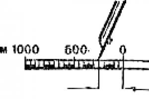
metal measuring ruler in accordance with GOST 427 with an upper measurement limit of 1000 mm, a limit of permissible deviation from the nominal values of the scale length and distances between any stroke and the beginning or end of the scale - 0.2 mm;
general purpose laboratory scales according to GOST 24104:
With the largest weighing limit of 5 kg, division value - 100 mg, standard deviation of the scale readings - no more than 50.0 mg, error from the uneven arm of the rocker - no more than 250.0 mg, margin of error - 375 mg;
With the largest weighing limit of 20 kg, division value - 500 mg, standard deviation of the scale readings - no more than 150.0 mg, error due to uneven arm - no more than 750.0 mg, margin of error - 1500 mg.
It is allowed to use other measuring instruments with metrological characteristics and equipment with technical specifications not worse than those specified in this standard.
6 Test preparation
6.1 A sample is made in the form of a rectangular parallelepiped, the largest (front) faces of which are in the form of a square with a side equal to the side of the working surfaces of the device plates. If the working surfaces of the device plates are in the shape of a circle, then the largest edges of the sample must also be in the shape of a circle, the diameter of which is equal to the diameter of the working surfaces of the device plates (Appendix A, clause A. 2.1).
6.2 The thickness of the test specimen shall be at least five times less than the length of the edge of the face or diameter.
6.3 The edges of the sample in contact with the working surfaces of the instrument plates must be flat and parallel. The deviation of the front faces of a rigid sample from parallelism should not be more than 0.5 mm.
Rigid samples with different thicknesses and deviations from flatness are ground.
6.4 The thickness of the parallelepiped sample is measured with a vernier caliper with an error of not more than 0.1 mm at four corners at a distance of (50.0 ± 5.0) mm from the top of the corner and in the middle of each side.
The thickness of the sample-disk is measured with a vernier caliper with an error of not more than 0.1 mm along generatrices located in four mutually perpendicular planes passing through the vertical axis.
The arithmetic mean of the results of all measurements is taken as the thickness of the sample.
6.5 The length and width of the sample in plan are measured with a ruler with an error of not more than 0.5 mm.
6.6 Regularity of the geometric shape and dimensions of the sample thermal insulation material determined according to GOST 17177.
6.7 The average size of inclusions (aggregate granules, large pores, etc.), which differ in their thermophysical parameters from the main sample, should not exceed 0.1 of the sample thickness.
It is allowed to test a sample with inhomogeneous inclusions, the average size of which exceeds 0.1 of its thickness. The test report shall state the average size of the inclusions.
6.8 Determine the mass of the sample M 1 upon receipt from the manufacturer.
6.9 The sample is dried to constant weight at the temperature specified in the normative document for the material or product. The sample is considered dried to constant weight if the loss of its weight after the next drying for 0.5 h does not exceed 0.1%. At the end of drying, the weight of the sample is determined. M 2 and its density r u, after which the sample is immediately placed either in a device for determining its thermal resistance, or in a sealed vessel.
It is allowed to test a wet sample at a cold face temperature of more than 273 K and a temperature difference of not more than 2 K per 1 cm of the sample thickness.
6.10 A sample of dried bulk material should be placed in a box whose bottom and lid are made of thin sheet material. The length and width of the box should be equal to the corresponding dimensions of the working surfaces of the plates of the device, the depth - the thickness of the test sample. The thickness of the bulk material sample must be at least 10 times the average size of the granules, grains and flakes that make up this material.
The relative hemispherical emissivity of the surfaces of the bottom and lid of the box shall be greater than 0.8 at the temperatures these surfaces experience during the test.
Thermal resistance R L sheet material from which the bottom and lid of the box are made should be known.
6.11 The sample of bulk material is divided into four equal parts, which are alternately poured into the box, compacting each part so that it occupies the corresponding part of the internal volume of the box. The box is closed with a lid. The lid is attached to the side walls of the box.
6.12 Weigh the box containing the bulk material sample. Based on the determined weight of the box with the sample and the predetermined values of the internal volume and the mass of the empty box, the density of the bulk material sample is calculated.
6.13 The error in determining the mass and size of samples should not exceed 0.5%.
7 Testing
7.1 Tests should be carried out on a previously calibrated instrument. The order and frequency of calibration are given in Appendix B.
7.2 Place the specimen to be tested in the instrument. Sample location - horizontal or vertical. With a horizontal sample, the direction of the heat flow is from top to bottom.
During the test, the temperature difference of the front faces of the sample D T u should be 10-30 K. The average temperature of the sample during testing should be indicated in the regulatory document for a specific type of material or product.
7.3 Set the specified temperatures of the working surfaces of the instrument plates and sequentially every 300 s measure:
heat meter signals e u and temperature sensors of the front faces of the sample, if the heat flux density through the test sample is measured using a heat meter;
the power supplied to the heater of the measuring zone of the hot plate of the device, and the signals of the temperature sensors of the front faces of the sample, if the heat flux density through the test sample is determined by measuring the electric power supplied to the heater of the measuring zone of the hot plate of the device.
7.4 The heat flow through the test sample is considered to be steady (stationary) if the values of the thermal resistance of the sample, calculated from the results of five successive measurements of the signals of the temperature sensors and the heat flux density, differ from each other by less than 1%, while these values do not increase and do not decrease monotonically.
7.5 After reaching a stationary thermal regime, measure the thickness of the sample placed in the device d u caliper with an error of not more than 0.5%.
7.6 After completion of the test, determine the mass of the sample M 3 .
8 Processing of test results
8.1 Calculate the relative change in mass of the sample due to its drying. T r and during testing T w and sample density r u according to the formulas:
Tr=(M 1 ¾ M 2 )/M 2 , (2)
Tw= (M 2 ¾ M 3 )/M 3 , (3)
Test sample volume V u calculated from the results of measuring its length and width after the end of the test, and the thickness - during the test.
8.2 Calculate the temperature difference of the front faces D T u and the average temperature of the test sample T mu according to the formulas:
D T u = T 1u ¾ T 2u , (5)
T mu= (T 1u + T 2u .)/2 (6)
8.3 When calculating the thermophysical parameters of the sample and the density of the stationary heat flux, the arithmetic mean values of the results of five measurements of the signals of the temperature difference sensors and the signal of the heat meter or electric power, performed after the establishment of a stationary heat flux through the test sample, are substituted into the calculation formulas.
8.4 When testing on a device assembled according to an asymmetric scheme, the thermal resistance of the sample R u calculated according to the formula
![]() (7)
(7)
Where Rk take equal to 0.005m 2 × K / W, and for heat-insulating materials and products - zero.
8.5 Effective thermal conductivity of the sample material l effu calculated according to the formula
 (8)
(8)
8.6 Thermal resistance R u and effective thermal conductivity l effu bulk material sample is calculated by the formulas:
![]() , (9)
, (9)
 . (10)
8.7 Stationary heat flux density q u through the sample tested on the device, assembled according to asymmetric and symmetrical schemes, is calculated, respectively, by the formulas:
q u = f u e u , (11)
![]() . (12)
. (12)
8.8 When testing on an instrument with a hot guard zone, in which the heat flux density is determined by measuring the electrical power supplied to the heater of the measurement zone of the hot plate of the instrument, thermal resistance, effective thermal conductivity and stationary heat flux density through the sample are calculated by the formulas:
![]() , (13)
, (13)
 , (14)
When testing bulk materials in formulas (13) and (14) instead of Rk substitute value R L ..
8.9 The test result is taken as the arithmetic mean of the thermal resistance and effective thermal conductivity of all tested samples.
9 Test report
The test report must contain the following information:
Name of material or product;
Designation and name of the normative document according to which the material or product is manufactured;
Manufacturer;
Batch number;
date of manufacture;
Total number of samples tested;
Type of instrument on which the test was carried out;
The position of the test specimens (horizontal, vertical);
Method for making samples of bulk material, indicating the thermal resistance of the bottom and lid of the box in which the samples were tested;
Dimensions of each sample;
The thickness of each sample before the start of the test and during the test, indicating whether the test was carried out at a fixed pressure on the sample or at a fixed sample thickness;
Fixed pressure (if it was fixed);
The average size of inhomogeneous inclusions in the samples (if any);
Sample drying technique;
The relative change in mass of each sample due to its day;
Humidity of each sample before and after the end of the test;
The density of each sample during the test;
The relative change in mass of each sample that occurred during the test;
The temperature of the hot and cold faces of each sample;
Temperature difference between hot and cold faces of each sample;
Average temperature of each sample;
The heat flux density through each sample after the establishment of a stationary thermal regime;
Thermal resistance of each sample;
Effective thermal conductivity of the material of each sample;
Arithmetic mean value of thermal resistance of all tested samples;
The arithmetic mean of the effective thermal conductivity of all tested samples;
Heat flow direction;
Date of testing;
Date of the last calibration of the device (if the test was carried out on a device equipped with a heat meter);
For standard samples used in the calibration of the device, the following must be indicated: type, thermal resistance, date of verification, validity period of verification, organization that carried out the verification;
Estimation of measurement error of thermal resistance or effective thermal conductivity;
A statement of full compliance or partial non-compliance of the test procedure with the requirements of this standard. If deviations from the requirements of this standard were made during the test, they should be indicated in the test report.
10 Error in determining effective thermal conductivity
and thermal resistance
The relative error in determining the effective thermal conductivity and thermal resistance by this method does not exceed ± 3% if the test is carried out in full accordance with the requirements of this standard.
APPENDIX A
(mandatory)
Requirements for instruments for determining the effective thermal conductivity and thermal resistance in a stationary thermal regime
A.1 Instrument diagrams
To measure the effective thermal conductivity and thermal resistance in a stationary thermal regime, the following instruments are used:
Assembled according to an asymmetric scheme, equipped with one heat meter, which is located between the test sample and the cold plate of the device or between the sample and the hot plate of the device (Figure A.1);
Assembled according to a symmetrical scheme, equipped with two heat meters, one of which is located between the test sample and the cold plate of the device, and the second - between the sample and the hot plate of the device (Figure A.2);
An instrument in which the heat flux through the test specimen is determined by measuring the electrical power supplied to the heater of the measuring zone of the instrument's hot plate (an instrument with a hot guard zone) (Figure A.3).

1 - heater; 2 - heat meter; 3 - test sample; 4 - fridge
Figure A.1 - Scheme of the device with one heat meter

1 - heater; 2 - heat meters; 3 - fridge; 4 - test piece
Figure A.2 - Scheme of the device with two heat meters

1 - fridge; 2 - test specimens; 3 - measurement zone heater plates;
4 - measuring zone heater winding; 5 - heater plates of the security zone;
6 - guard zone heater winding
Figure A. 3 - Diagram of a device with a hot security zone
A.2 Heater and cooler
A.2.1 Heater or cooler plates may be in the form of a square, the side of which shall be at least 250 mm, or a circle, the diameter of which shall not be less than 250 mm.
A.2.2 The working surfaces of the heater and cooler plates must be made of metal. The deviation from the flatness of the working surfaces should be no more than 0.025% of their maximum linear size.
A.2.3 The relative hemispherical emissivity of the working surfaces of the heater and cooler plates in contact with the test sample should be more than 0.8 at the temperatures that these surfaces have during the test.
A.3 Heat meter
A.3.1 The dimensions of the working surfaces of the heat meter should be equal to the dimensions of the working surfaces of the heater and refrigerator plates.
A.3.2 The relative hemispherical emissivity of the front face of the heat meter in contact with the test specimen shall be greater than 0.8 at the temperatures that this face has during the test.
A.3.3 The measurement zone of the heat meter should be located in the central part of its front face. Its area should be at least 10% and not more than 40% of the total area of the front face.
A.3.4 The diameter of thermocouple wires used in the manufacture of the thermoelectric battery of the heat meter should be no more than 0.2 mm.
A.4 Temperature sensors
The number of temperature sensors on each working surface of the heater or refrigerator plates and the front face of the heat meter in contact with the test sample must be equal to the integer part of the number 10 Ö A and be at least two. The diameter of the wires suitable for these sensors should be no more than 0.6 mm.
A.5 Electrical measuring system
The electrical measuring system must ensure the measurement of the signal of the surface temperature difference sensors with an error of not more than 0.5%, the signal of the heat meter - with an error of not more than 0.6%, or the electric power supplied to the heater of the measurement zone of the hot plate of the device - with an error of not more than 0 .2%.
The total error in measuring the temperature difference between the surfaces of the plates of the device and the heat meter in contact with the front faces of the test sample should not be more than 1%. Total error - the sum of errors arising from the distortion of the temperature field near the temperature sensors, changes in the characteristics of these sensors under the influence of external conditions and the error introduced by the electrical measuring system.
A.6 Apparatus for measuring the thickness of the test piece
The device must be equipped with a device that allows measuring the thickness of the sample during its testing with a caliper with an error of not more than 0.5%.
A.7 Instrument frame
The device must be equipped with a frame that allows you to maintain different orientations in the space of the device block containing the test sample.
A.8 Device for fixing the test specimen
The device must be equipped with a device that either creates a constant predetermined pressure on the test sample placed in the device, or maintains a constant gap between the working surfaces of the device plates.
The maximum pressure created by this device on the test sample should be 2.5 kPa, the minimum - 0.5 kPa, the pressure setting error - no more than 1.5%.
A.9 Device for reducing lateral heat loss or heat gain of the test piece
Lateral heat losses or heat gains during the test must be limited by isolating the side faces of the test sample with a layer of heat-insulating material, the thermal resistance of which is not less than the thermal resistance of the sample.
A.10 Instrument casing
The instrument shall be provided with an enclosure in which the air temperature is maintained equal to the average temperature of the test specimen.
APPENDIX B
(mandatory)
Calibration of a device equipped with a heat meter
B.1 General requirements
The calibration of an instrument equipped with a heat meter should be carried out using three duly certified standard thermal resistance samples made, respectively, of optical quartz glass, organic glass and foam plastic or fiberglass.
The dimensions of the standard specimens shall be equal to the dimensions of the specimen to be tested. In the process of calibrating the instrument, the temperature of the front faces of the standard samples must be respectively equal to the temperatures that the front faces of the test sample will have during the test.
The entire range of thermal resistance values that can be measured on the device should be divided into two sub-ranges:
the lower limit of the first subrange is the minimum value of thermal resistance that can be measured on this device; upper limit - the value of thermal resistance of a standard sample made of organic glass and having a thickness equal to the thickness of the sample to be tested;
the lower limit of the second subrange is the upper limit of the first subrange; upper limit - the maximum value of thermal resistance that can be measured on this device.
B.2 Calibration of a device assembled according to an asymmetric scheme
Prior to calibration, one should evaluate the numerical value of the thermal resistance of the sample to be tested according to known reference data and determine which subrange this value belongs to. The calibration of the heat meter is carried out only in this subrange.
If the thermal resistance of the sample to be tested belongs to the first subrange, the calibration of the heat meter
carried out using standard samples made of optical quartz and organic glass. If the thermal resistance of the sample belongs to the second subrange, the calibration is carried out using standard samples made of organic glass and heat-insulating material.
Place the first standard sample with the lower thermal resistance into the instrument. R S 1 , D T 1 of its front faces and the output signal of the heat meter e 1 according to the procedure described in section 7. Then a second standard sample with a large thermal resistance is placed in the instrument R S 2 , measure temperature difference D T 2 of its front faces and the output signal of the heat meter e 2 by the same method. Based on the results of these measurements, calibration coefficients are calculated f 1 and f 2 heat meters according to the formulas:
The value of the calibration coefficient of the heat meter f u , corresponding to the value of the heat flux flowing through the test sample after the establishment of a stationary heat flux, is determined by linear interpolation according to the formula
![]() . (B.3)
. (B.3)
B.3 Graduation of a device assembled according to a symmetrical scheme
The method for determining the calibration coefficient for each heat meter of the device assembled according to a symmetrical scheme is similar to the method for determining the calibration coefficient for a heat meter described in B.2.
B.4 Frequency of instrument calibration
The calibration of the instrument shall be carried out within 24 hours preceding or following the test.
If, according to the results of calibrations carried out within 3 months, the change in the calibration coefficient of the heat meter does not exceed ± 1%, this device can be calibrated once every 15 days. In this case, the test results can be transferred to the customer only after the calibration following the test, and if the value of the calibration coefficient determined from the results of the subsequent calibration differs from the value of the coefficient determined from the results of the previous calibration by no more than ± 1%.
The calibration coefficient used in calculating the thermophysical parameters of the test sample is determined as the arithmetic mean of the two indicated values of this coefficient.
If the difference in the value of the calibration factor exceeds ± 1 %, the results of all tests carried out between these two calibrations are considered invalid and the tests must be repeated.
APPENDIX B
Bibliography
ISO 7345:1987 Thermal insulation. Physical quantities and definitions
ISO 9251:1987 Thermal insulation. Heat transfer modes and material properties
ISO 8301:1991 Thermal insulation. Determination of thermal resistance and related thermophysical indicators in a stationary thermal regime. Appliance equipped with a heat meter
ISO 8302:1991 Thermal insulation. Determination of thermal resistance and related thermophysical indicators. Device with hot guard zone
Keywords: thermal resistance, effective thermal conductivity, standard sample
Introduction
1 area of use
3 Definitions and notation
4 General provisions
5 Measuring instruments
6 Test preparation
7 Testing
8 Processing of test results
9 Test report
10 Error in determining the effective thermal conductivity and thermal resistance
Annex A Requirements for instruments for determining the effective thermal conductivity and thermal resistance in stationary thermal conditions
Appendix B Calibration of an instrument equipped with a heat meter
Appendix B Bibliography