Beautiful large LED chandelier with your own hands. How to make fiber optic lighting with your own hands? Homemade fiber optic cable
Good day, brainfriends! Progress does not stand still and now you will not surprise anyone with such a thing as optical fiber, which, due to its characteristics, is great for creating original crafts. For example, like the stylized lamp from this guide.
The brain project this is my first fiber optic homemade which I was inspired by this one.
I decided to make a tree because I have a hammock and I thought it would be nice to have a tree with it.
Again, this is my first time working with fiber, and to fully focus on design homemade rather than "messing" with basic fiber techniques, I was forced to use a finished product that already included the LED light source, control components, and the fiber itself. But in the future I plan to create a chandelier using fiber optics completely from scratch.
After all the necessary materials are found, the assembly of the fiber optic tree-lamp itself will take about one to two days, depending on the complexity. brain crafts. This requires only basic skills in working with tools and electrical components, in addition, I still think that this is an easy project, and I think it will be interesting for teenagers.
Design homemade is variable, and it will most likely take some time to figure out how your "glowing" tree will look.
Step 1: Materials
- "starry sky" fiber optic preform, I chose this one (the 1W LED does not give much light, it's more of a backlight than a luminaire, but I couldn't find a warm white fiber optic preform),
- case for electrical components (I used a praline box) and the way to make holes in it (it depends on the material of the case), it will be great if the case has a lid, this will facilitate assembly and possibly give a place to store the remote control, and it is also desirable that the hull was incombustible,
- hot glue (I needed three rods)
- a suitable rail to keep the barrel upright and to be able to attach it to the wall,
- metal wire to create the barrel (I chose rusty wire to make the barrel brown), the wire is about 1mm in diameter so that it can hold its shape under the fiber,
- some electrical components, such as a socket, a cable, and optionally a switch,
- a small piece of sandpaper to strip the fiber in some places to give the craft more organicity,
- improvised tools, such as a screwdriver, knife, pliers and clothespins,
- tools and materials for attaching crafts to the wall, such as a drill, screws and dowels
- and optionally, to create a storage place for the remote control - a grocery grid, 20cm-in ropes, an eyelet, a hole punch and a riveter.

Step 2: Electrical Enclosure

We make holes in the selected case:
- to mount it on the wall
- one hole for the power cable
- one or more holes for outputting optical fiber.
Regarding the holes for the fiber - their edges should not damage the fiber itself, for this I covered the edges of the holes with hot glue, in my case the fiber comes out in 4 bundles, so I made 4 holes, respectively.
Can be dyed upon request braincase so I painted it the same color as my wall.
Step 3: Remote Pouch (Optional)

Having folded the label of the onion net, I made a hole in this label with a hole punch, and using a riveter, I installed a grommet in it.
After that, he put the remote control into the net brain crafts and tied it with a rope.
Step 4: Connecting electrical components
On request, you can on the body homemade or install a switch on the power cable suitable for it. I didn't because I had a switch on the wall itself.
My power cord coming from the switch didn't have an outlet, so I had to buy one and place it in the craft case. IMPORTANT NOTICE: if your tree lamp body is metal, make sure that all electrical components are well insulated! And during everything brain project NEVER insert bare wires into the socket, as I did!
Step 5: Attaching the Rail to the Chassis

In order not to break brainlight, if you decide to move it, and in order to simplify the creation of the trunk, I decided to attach a rail to the body with hot glue.
Step 6: Placing the Fiber Optic Preform in the Chassis


At this stage, it is necessary to determine how the fiber optic preform will be placed in the package. Then, through the previously drilled holes, skip the fiber bundles, if the holes come out of a small diameter, then an impromptu paper funnel can help with this, like me.
After that, you need to fix the fiber-optic blank in the case with the same hot glue, and then place, connect and fix all other electrical components.
Step 7: A Minute of Botany


In order for your tree to turn out much better than mine, it is advisable to take a walk and look at the structure of real trees.
Step 8: Preparing the Wire


Now you need to decide on the number of pieces of wire that will serve as the trunk and branches, I used ten pieces. Just decide how long your tree will be from the very horses to the top, add another 20% and cut the required number of pieces of this length, they were about 1 meter for me.
Note: thin branches without proper support will sag, so if you decide to make some other tree than a weeping willow, then make sure that your structure will be strong enough, and even the smallest branches consist of several pieces brainwires.
Working with wire is not so easy, but you still have to do it. It is necessary to take all the pieces of wire and twist them together from one end, which will be the "roots". One piece needs to be threaded through/around the rail to attach the barrel.
Step 9: Weave the trunk and branches

The barrel is formed by twisting the fiber and wrapping pieces of wire around it, periodically wrapping a rail in some places so that the barrel can withstand the load, and in order to make it look more natural, the barrel should be made slightly curved.
When the fiber is bent or pressed against something, these places emit light, so when forming the trunk and branches, it is necessary to twist and press the optical fibers so that the trunk and branches glow, but the fibers themselves are not damaged. If you are not completely sure of yourself, then turn on the future tree so that you get an idea of \u200b\u200bwhat you are doing.
The metal tips of the branches must be formed into rings to prevent the fiber from unwinding, and to avoid injury if someone touches the tree. homemade.
How the tree should look depends on the type of "tree", see Step: Botany Minute. For my "weeping willow" I hung three or four fibers from the branches.
Step 10: Weeping Branches


It's time to turn on the almost ready brainwashing. If you like everything about it, then you can cut the fibers and proceed to the step "Mounting crafts on the wall."
Things with fiber optics always remind me painfully of the scenery of the 80s, and I want my glowing tree to look more organic. To do this, do the following:
- sandpaper to clean the fiber in some places so that it glows in them and more like tree bark,
- apply droplets of hot glue to the tips of the fiber of thin branches, this will make them heavier and they will also begin to scatter light more. You need to be careful when doing this and first practice applying the glue to the ends to be cut to get an idea of how much of this glue needs to be applied before it starts to melt the fiber. I, in turn, found that it was worth gluing three or four fibers together with such droplets of glue at once, so that luminous “dreadlocks” began to hang from my tree.
Excess fiber must be cut to your liking, that is, make brainwash"haircut".
Step 11: Attaching the craft to the wall


For fastening crafts on the wall, attach a luminous tree to the desired section of the wall and mark the places for the mounting holes, drill them with appropriate drills, and attach them using dowels and screws homemade.
At your discretion, when screwing in the screws, one of them can be attached to the mesh through the grommet of the label.
It remains to give the tree its final look, bending the branches and roots in such a way that everything looks beautiful, and at the same time it was not traumatic.
And now turn on do-it-yourself brain and enjoy!
With all the advantages of optical fibers, for the installation of networks they must be connected. It is the complexity of this process for quartz glass light guides that is the main limiting factor in fiber optic technology.
Despite all the progress in technology in recent years, non-professionals can only connect cables that do not have special quality requirements. Serious work on the installation of highways of regional importance requires expensive equipment and highly qualified personnel.
But to create an inter-house wiring of the "last mile" such difficulties are no longer needed. The work is available to specialists without serious training (or without it at all), a set of technological equipment costs less than $300. In combination with this, the huge (I dare not be afraid of this word) advantages of optical fiber over copper cables in overhead installations make it a very attractive material for home networks.
Let us consider in more detail the types and methods of connecting optical fibers. To begin with, it is necessary to fundamentally separate splices (one-piece connections) and optical connectors.
In relatively small networks (up to several kilometers in diameter), splices are not desirable and should be avoided. Today, the main method of their creation is electric discharge welding.
The principle of optical fiber welding.

Such a connection is reliable, durable, and introduces negligible attenuation into the optical path. But welding requires very expensive equipment (in the region of several tens of thousands of dollars), and a relatively high qualification of the operator.
This is due to the need for high-precision alignment of the ends of the fibers before welding, and maintaining stable parameters of the electric arc. In addition, it is necessary to provide even (and perpendicular to the fiber axis) ends (cleaves) of the fibers to be welded, which in itself is a rather difficult task.
Accordingly, the implementation of such work "from time to time" on your own is not rational, and it is easier to use the services of specialists.
Also, a similar method is often used to terminate cables by welding cable fibers with small pieces of flexible cables with connectors already installed (pig tail, literally - a pig's tail). But with the spread of adhesive joints, welding is gradually losing ground when terminating lines.
The second way to create permanent connections is mechanical, or using special connectors (splices). The original purpose of this technology is a fast temporary connection used to restore line performance in the event of a break. Over time, for "repair" splices, some companies began to give a guarantee of up to 10 years, and up to several tens of connection-disconnection cycles. Therefore, it is advisable to separate them into a separate method for creating permanent connections.
The principle of operation of the splice is quite simple. The fibers are fixed in a mechanical conductor, and are brought closer to each other with special screws. For good optical contact, a special gel with optical properties similar to quartz glass is used at the junction.
Despite the external simplicity and attractiveness, the method is not widely used. There are two reasons for this. Firstly, it is still noticeably inferior in terms of reliability and durability to welding, and is not suitable for backbone telecommunication channels. Secondly, it is more expensive than mounting adhesive connectors and requires more expensive technological equipment. Therefore, it is rarely used when installing local networks.
The only thing in which this technology is unparalleled is the speed of work, and not exacting to external conditions. But this is clearly not enough today to completely conquer the market.
Consider detachable connections. While the range limit of high-speed twisted-pair power lines depends on the connectors, in fiber optic systems, the additional losses introduced by them are quite small. Attenuation in them leaves about 0.2-0.3 dB (or a few percent).
Therefore, it is quite possible to create networks of complex topology without the use of active equipment by switching fibers on conventional connectors. The advantages of this approach are especially noticeable on small but branched "last mile" networks. It is very convenient to divert one pair of fibers for each house from the common backbone, connecting the remaining fibers in the "through" junction box.
What is the main thing in a detachable connection? Of course, the connector itself. Its main functions are to fix the fiber in the centering system (connector), and protect the fiber from mechanical and climatic influences.
The main requirements for connectors are as follows:
introduction of minimum attenuation and back reflection of the signal;
minimum dimensions and weight with high strength;
long-term operation without deterioration of parameters;
ease of installation on the cable (fiber);
ease of connection and disconnection.
Today, several dozen types of connectors are known, and there is no one that would be strategically oriented for the development of the industry as a whole. But the main idea of all design options is simple and quite obvious. It is necessary to precisely align the axes of the fibers, and tightly press their ends to each other (create contact).
The principle of operation of the fiber optic connector of the contact type.

The bulk of the connectors are produced in a symmetrical pattern, when a special element is used to connect the connectors - a coupler (connector). It turns out that at first the fiber is fixed and centered in the tip of the connector, and then the tips themselves are centered in the connector.
Thus, it can be seen that the signal is affected by the following factors:
Internal losses - caused by tolerances on the geometric dimensions of the optical fibers. These are the eccentricity and ellipticity of the core, the difference in diameters (especially when connecting fibers of different types);
External losses, which depend on the quality of the connectors. They arise due to the radial, angular displacement of the tips, the non-parallelism of the end surfaces of the fibers, the air gap between them (Fresnel losses);
Reverse reflection. Occurs due to the presence of an air gap (Fresnel reflection of the light flux in the opposite direction at the glass-air-glass interface). According to the TIA / EIA-568A standard, the reverse reflection coefficient is normalized (the ratio of the power of the reflected light flux to the power of the incident light). It should be no worse than -26 dB for single-mode connectors, and no worse than -20 dB for multi-mode;
Contamination, which in turn can cause both external loss and back reflection.
Despite the absence of a connector type officially recognized by all manufacturers, ST and SC are actually common, very similar in their parameters (attenuation 0.2-0.3 dB).
Optical fiber connectors.

ST. From the English straight tip connector (straight connector) or, informally, Stick-and-Twist (insert and turn). It was developed in 1985 by AT&T, now Lucent Technologies. The design is based on a ceramic tip (ferule) with a diameter of 2.5 mm with a convex end surface. The plug is secured to the socket by a spring-loaded bayonet element (similar to BNC connectors used for coaxial cable).
ST connectors- the cheapest and most common type in Russia. It is slightly better than the SC in terms of tough environments thanks to its simple and strong metal construction (allows more room for brute force).
As the main disadvantages, one can name the complexity of marking, the laboriousness of connection, and the impossibility of creating a duplex plug.
SC. From the English subscriber connector (subscriber connector), and sometimes the unofficial decryption Stick-and-Click (insert and snap) is used. It was developed by the Japanese company NTT, using the same ceramic tip as in ST, with a diameter of 2.5 mm. But the main idea is a lightweight plastic body that protects the tip well and provides smooth connection and disconnection in one linear motion.
This design allows a high density of mounting, and easily adapts to convenient dual connectors. Therefore, SC connectors are recommended for creating new systems, and are gradually replacing ST.
Additionally, two more types should be noted, one of which is used in a related industry, and the other is gradually gaining popularity.
FC. Very similar to ST, but with a threaded lock. It is actively used by telephonists of all countries, but practically does not occur in local networks.
LC. New "miniature" connector, structurally identical to SC. So far, it is quite expensive, and its use is meaningless for "cheap" networks. As the main argument "for" the creators cite a high density of editing. This is a serious enough argument, and in the distant (by telecommunications standards) future it is quite possible that it will become the main type.
To carry out lighting in any bath, especially a steam room, is not an easy task, since in such rooms the most unfavorable environment for electrical engineering: high temperature, constant humidity, vaporization. Especially for baths, fiber-optic models of lamps were developed, which make it possible to do without electrical wiring in the steam room.
In this article:
Design features of fiber optic lighting devices
For such lighting equipment, the ability of glass to supply a luminous flux over fairly long distances is used with virtually no loss. As a rule, long threads are made from glass, which are called fibers. Then they are collected in one bundle, wrapped (or not) in a special protective sheath.
Expert opinion
Ivan Zaitsev
Lighting specialist, consultant in the building materials department of a large retail chain
Ask an expertFor your information! If the glass fiber is homogeneous, without any defects, its light transmission range can be kilometers. Of course, the production of such conductors, unlike conventional ceiling chandeliers, is quite expensive, so the use of fiber-optic lighting devices in everyday life is limited.

But developers have found a way to reduce the cost of fiber optic production technology. For this, a polymeric material - acrylic was used. Such an optical conductor is also not cheap, but it costs several times less than glass.
Principle of operation
How do lighting systems of this design function? As a rule, a projector emitter equipped with special filter elements is fixed at one end of the fiber optic cable. As a result, light transmission is carried out by fiber optic strands on one side opposite to the fiber optic strands. Visually, light rays can be observed on sections of fiber optic strands. In order to provide a different shape to the glow, small lenses are put on each such thread that scatter the emitted light.
Light intensity will depend on the following factors:

For your information! Fibers are made, the walls of which also glow (if there is no insulation).
System Composition
Fiber optic lamps are most often sold in kits, which include the following components:
- Projector. This is a special installation of small dimensions - the only structural element that is connected to a power source. The projector uses gas discharge, halogen, LED lamps. Additionally, you can use: a trigger, a voltage converter, several different lenses for changing colors, and other parts. The level of illumination of the room will depend on the number of additional elements, the power of the light source.
- Optical threads - fibers. They create a directed luminous flux (in the sheath), they are also capable of forming a linear-type glow along the entire length of the fiber optic thread. There are options for point glow along the fiber optic strand. The brightness of the light flux primarily depends on the diameter of the fiber optic thread, the power of lighting equipment, in this case a projector with lamps.
For your information! The number of fibers can be calculated in units and thousands of fiber optic strands. The lighting of the steam room is achieved precisely by a combination of threads with different characteristics.

For your information! There are also a variety of rotary, movable parts, mechanisms for adjusting the intensity of the light flux, which can be additionally installed on lighting devices. .
When planning to organize fiber-optic lighting of a country bath with your own hands, it is recommended to select lighting equipment of this category not only in terms of the number and length of the fibers. It is necessary to pay attention to the light source used - GL, GRL, LED.
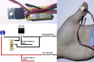
If there are gas-discharge, halogen lamps in the spotlight, it is necessary to check the operation of the cooling fan. There are quite noisy models that can spoil the rest. Therefore, it is recommended to purchase projectors with led elements that do not heat up at all, so they do not require cooling.
What made by hand costs about $200 and looks much better! In addition, the chandelier is controlled by a remote control and can be successfully used for information notification.
Note : Sometimes the photos do not exactly match what is described in the step.


Step 1: Equipment and Tools

- Sheets of black plexiglass 50*50cm and thickness 4-6 mm.
- 200 glass beads diameter 1.7cm;

- 3 W RGB LEDs with remote control;
- Plastic container;

- Heat shrink tubing;
- IR receiver;
- Epoxy adhesive;

- Chain;
- transition pipe;
- 120 m fiber optic cable;

- wires;
- Adhesive tape;
- Black paint;

- screws;
- Three-pin electrical plug/socket;
- Lamp socket.

Tools:

- grinding disc;
- Drill and drills;
- Hot glue gun;
- Engraver with nozzle;
- Saw;
- Electric jigsaw;
- Varnish and paint brushes;
- Hacksaw;
- Plane;
- Compass;
- Vise;
- Plasticine;
Step 2: Wood Base Top - Part 1
Using a compass, draw a circle with a radius 225 mm. Then cut it out with a hacksaw.

We grind the edges of the circle with a disc grinder.

To complete the decoration, paint the upper side black (in three layers).
Electronics :
Cut a hole large enough to accommodate a three-prong socket.

Then fix it with screws.
Set the plastic box on the wooden circle. Drill holes for four short 7 mm screws.

Connect the wires from the power supply to the lamp base.
The photo does not take into account the fact that the lamp is in a plastic box. Since these photos were taken after the project was completed.

Step 3: Wood Base Top - Part 2
Let's take a chain and cut it into three sections, each of them is 25 cm.

In a wooden base, drill three holes in 20 cm from the center. These holes, if properly drilled, will form an equilateral triangle.

Insert the eye stud (with a washer on the top and bottom) into the drilled hole and tighten with a nut.

Place the ends of the chains in each loop.

Install the opposite ends in carabiners.

The suspension mechanism is ready.

The support posts will support the Plexiglas plates.
Use a planer and sandpaper to make the surface of the bar smooth.

Apply varnish to the supporting parts to further protect them from moisture.
Let's make marks on the bar every 7 cm(a total of 42 cm), and then cut the workpiece into 6 parts.

Now we will place six hexagon-shaped blocks along the lines on the plexiglass plates between the 3rd and 4th rings.
The last photo is the only picture that shows exactly how all the supports should look at the end of all the operations done.

Step 4: Perspex Plate - Part 1

Draw a circle with a radius 225 mm.
Use a jigsaw to cut out the circle and a sander to clean up the edges.

Now you need to divide the workpiece into five rings. They will separate the chandelier, creating multi-level transitions.
Workpiece marking:

- Draw the first circle with a diameter 205 mm, slightly scratching the circle, then draw the outline with a pencil;
- The second circle is the radius 160 mm;
- Third circle - radius 115 mm;
- The fourth circle is the radius 70 mm;
- Fifth circle - diameter 50 mm.
The width between the marks on the circles is 20 mm.
Step 5: Perspex Plate - Part 2

The circumference of the fifth ring = diameter (5 cm) x π = 15.7 cm. (Round the number to avoid any error when working with tools).
Diameter of each glass ball 1.7 cm. Therefore: 15.0 / 1.7 = 8 pcs. The ring used 7 balls to create a small gap between each element.

Repeat this procedure for each ring, making sure to leave the required gap between the balls.
It's time to make marks on the rings where the balls will be located.

To do this (the fifth ring is considered as an example), we take 7 glass balls, plasticine and attach the balls to the workpiece. After that, we circle their outline with a pencil.
Make sure the pencil is perpendicular to the base. After that, mark the centers of future holes.
Repeat this procedure for the remaining four rings.
After all places are marked, using a drill 0.5 mm drill a hole.
Step 6: Light Box

The light source and receiver are inside the box.
Mark the center at the end of the plastic box. We drill a hole of the same cross section as the diameter of the base. Install the pipe adapter on the opposite end of the box.

Now let's install the IR sensor on the pre-existing terminal. (Sorry, no photo).
We cut three wires with a length of 20 cm every.

Clean up the ends of the wires.
Let's connect one wire to the lead to an existing IR sensor
Close the connection with heat shrink tubing and then twist it with wire (no soldering required).

Attach the appropriate wires to the IR sensor and apply heat shrink tubing.
Install the lamp in the light box and close it. Now we can screw the light box onto the wooden base using the screws and pilot holes we made earlier.
Step 7: Mounting the Balls

In this step, we will use an engraver with a spherical nozzle.
Let's make a conductor that will hold the balls (two clamps are attached to the wood). The whole structure is very stable, in addition, it allows you to work freely with tools.

Let's repeat the procedure 180 times!!! Yes, I know it will take the most time, but be patient even when some of them break...
Step 8: Cut the fiber

Exists 5 levels optical fiber.
Using a centimeter and scissors, cut the fiber in accordance with the table:
- 7x - 75 cm of thread + 10 cm = 85 cm each;
- 21x - 60cm thread + 15cm = 75cm;
- 35x - 45cm thread + 20cm = 65cm;
- 50x - 30cm thread + 25cm = 55cm;
- 64x - 15cm thread + 30cm = 45cm.
CAUTION!: This is the length of each fiber, including the bead. In order for each layer to connect to the light box, you must add extra length to the fiber to mount it into the system.
Step 9: Installing the Threads

Let's pick up the bundles. For example, 7x 85cm or 50x 55cm will be joined with heat shrink tubing to hold them together. Repeat these steps for all other groups.

Take 7x 85cm of yarn and thread each strand through the hole on the inner ring of the bottom plate.


You must pull all the threads through one hole! This will allow much better light transmission and mount the threads in a closed case.

To make an even end cut, heat the spatula with a blowtorch until it is hot enough to melt the fibers.

Step 10: Installing the Balls


For fastening, you must use epoxy, not super glue.


Set the fibers in the hole and press everything down with tape to make a small cradle for the ball. The cradle should “hug” the ball and bear the weight of the glass, thus allowing the glue to dry. I recommend wrapping with a second layer of tape to avoid the chance of losing stiffness.


The final effect is that you don't see the glue, the fiber magically touches the glass when viewed from below and from the side.

Step 11: Basic Decorations

Pieces of plexiglass long 303 mm, divided into 3 parts and cut with a band saw, their width is 30 mm.

Divide the squares into 3 equal parts

Use a saw to cut out these rectangles

Take off the paper from the plexiglass

We attach the plates with superglue to the wooden base, use a square for precise alignment.

Repeat this procedure for all 47 pieces.
Step 12: End result


This turned out to be unusual craft —
From the hundreds of ceiling lighting solutions, some people tend to choose the most unusual ones. The lighting design, made in the form of a starry sky, is an idea that deserves attention.
naumov FORUMHOUSE User,
Moscow.
A friend in the nursery saw a diode sky as a secondary backlight. It has an unusual geometry and is made using LEDs of various colors. He also has some kind of system that alternately some diodes (not in waves, but in a random sequence) begin to slowly go out. It looks very nice, and the child falls asleep instantly. Backlight - the starry sky is lit all night.
There are many ideas related to the implementation of such an unusual lighting solution. They differ in the complexity of the design, its cost, design, complexity and variety of special effects. Among the most common design solutions are LED star suspended ceiling and fiber optic lighting. We recommend using a structure during construction that involves the use of fiber optic strands and a light projector (mechanical or electronic). It is technically simpler, cheaper and more reliable.

Electro FORUMHOUSE user
LEDs are good, but extremely expensive. It is better to use the starry sky on the principle of optical fiber.

You need to understand the difference between backlighting and lighting. The functions of the ceiling in the form of a starry sky should not go beyond the backlight.
FDRA FORUMHOUSE user
It is inappropriate to consider the starry sky as the main illumination. It is better to separate the concepts of lighting and highlighting. The starry sky should only be used as interior lighting. It seems to me that this would be a more correct and budget solution. And the starry sky will remain STARRY, and not studded with lamps.
Stretch ceilings are the basis for creating star lighting. But this does not mean that star lighting cannot be mounted in a plasterboard ceiling (in this case, the gypsum board will serve as a good screen and a reliable basis for installed communications). For the design of stretch ceilings, both fabric fabrics and PVC structures are suitable.
PVC films have their own advantages when creating such finishing solutions as a stretch ceiling with "star" illumination. This is due to the properties of the presented material: it is easier to apply decorative coatings on it in the form of photo printing or airbrushing. Ideally, you should use matte or satin canvases, on the surface of which you can pre-imprint all kinds of space objects.
Fabric ceilings are remarkable in that the pattern on their surface can be used as a marking that allows you to accurately bring the optical fiber out. The image of the starry sky is applied to such a canvas by the method of interior printing. The most amazing thing is that the image of the real night sky, photographed with a telescope, can be applied to the fabric ceiling.
Star fiber based ceiling
To date, there are several ways to create a ceiling in the form of a starry sky, using optical fiber and a light generator. All of them involve the installation of fiber optic strands and a light projector.

The simplest example of illumination using the listed components is a lamp familiar to many readers, the cap of which consists of translucent hairs shimmering in various colors. By introducing similar threads of different thicknesses (0.5 ... 3 mm) into the design of a stretch ceiling, you can easily simulate the light of distant stars with different brightnesses. Fiber optic strands are placed in the space between the main ceiling and the stretch ceiling canvas. Sometimes they are brought outside, and sometimes they are completely hidden under the canvas.
The output of the optical fiber through the web to the outside guarantees the creator of the ceiling certain advantages. They lie in the fact that the stars on the ceiling burn much brighter, they are clearly visible even during daylight hours. But be aware: if the projector illuminating such a structure is turned off, then each thread (if it is cut flush with the canvas) will look like a dark dot on the ceiling (especially if the ceiling is low). Therefore, if you like this option, then it should be implemented in conjunction with photo printing. If this is not possible, then dark-colored canvases must be used. Following these tips, you can mask the punctures in the ceiling as much as possible.
If you decide not to thread the fiber through the stretch ceiling, then the light of the "constellations" will ideally be visible only in complete darkness, the glow will turn out to be slightly diffused. But the integrity of the canvas in this case will not suffer, and the threads sticking out of it will not spoil the appearance of the ceiling during the day. In order for the light to appear brighter, a larger diameter fiber (1-2 mm) should be used.
Mounting the backlight with threading through the canvas
First of all, you need to choose a place for the projector. It should not be completely hidden under the ceiling canvas, because the need to replace the lamp or eliminate any malfunction will arise sooner or later. For its installation, a plasterboard niche framing a stretch ceiling is best suited. You can use a functional drywall box or, in extreme cases, a special recess in the wall. In all cases, it is necessary to provide access to the device through a closing hatch.

At the next stage, we attach a paint grid to the surface of the base ceiling.

After that, the fiber optic strands should be passed through the mesh in those places where luminous objects will be located on the plane of the stretch ceiling.

Sharp bends in the fiber should be avoided, as this may affect the quality of the backlight.
After the fiber is threaded through the mesh, its free ends are tied together, cut evenly, and the resulting beam is connected to a light generator. After connecting the projector to the mains, you need to make sure that all the fibers glow.

At the next stage, you can begin to install the stretch ceiling and thread the threads through its canvas. The first step is to fix one corner of the canvas on a pre-installed baguette. Given that the canvas is first attached to the corners of the room, it is necessary to warm it up diagonally and fix it in two opposite corners. Now you can thread the threads, starting from the middle of the room. Immediately take note that you cannot do without an assistant in this matter.
Holes in the canvas can be made with fiber optic strands, cutting their ends at 45 °. But in most cases, punctures are made with an ordinary needle or a thin awl.
One or more threads are pulled into each hole (depending on the design idea). The ends of the threads should protrude by 15 cm, but for convenience during installation work, you can leave longer ends.
It is impossible to pull the threads too much, it is better to leave a margin of their length. This will allow easy insertion and removal of the fiber bundle from the projector, avoiding many of the inconveniences associated with length restrictions.
As the threads are threaded through the surface of the canvas, the rest of it should be attached to the baguette (do not forget that the corners are attached first).
After the ceiling is mounted, the threads, for reliability, can be fixed on the surface of the canvas with transparent glue. But it is not necessary to do so.
The optical fiber can be left in the form of short hanging strands.

If desired, after the installation work is completed, the threads can be cut. Some cut them flush with the ceiling, while others leave the glowing ends outside.

In order to create the effect of the glow of larger stars, the ends of the fiber should be cut evenly and soldered to their edges with a soldering iron.

Mounting the backlight without threading
In the case of mounting the backlight without threading, all the elements of the backlight will look like this:

This option is somewhat more complicated than the previous one, because it requires the installation of a false ceiling made of plasterboard, plywood, foam plastic or other sheet material mounted between the base ceiling and the stretch ceiling canvas. Holes are sequentially made in it, through which the fiber optic threads will be pulled. Threads (or bundles of threads) are fixed on the upper surface of the false ceiling. Their lower ends will rest against the canvas of the stretch ceiling, practically not being able to move to the side. Several LEDs with different power can be attached to the ends of the fiber. This will create the effect of the glow of large celestial bodies (asteroids, comets, etc.).
After installing the false ceiling, the fixed ends of the optical fiber are cut evenly. This will allow them to evenly adhere to the surface of the lower canvas.

When creating backlight without threading, you should use fabrics with maximum light transmission.
Star illumination with Swarovski crystals
If you think that the ceiling of your apartment deserves the best design, there is a solution that allows you to make it perfect lighting. We are talking about Swarovski crystals, which are able to perfectly scatter light from an optical fiber.

With the help of special reinforced rings, these objects are attached to the lower surface of the stretch ceiling. Then one or more fiber optic strands are inserted into them. This allows you to get several clear and bright rays cast in different directions. Thanks to Swarovski crystals, you can create bright constellations and implement no less extravagant design ideas.

Varieties of projectors
The effects created with its help directly depend on which light generator is used in the design of the stretch ceiling. There are two main varieties of projectors used to create a star ceiling. These are mechanical and electronic devices. In mechanical projectors, a small electric motor rotates a special light filter, which, in turn, changes the color of the light flux. In electronic devices, color is controlled by LEDs controlled by a controller that operates in accordance with a given program.
Despite the fact that the mechanical projector is a little noisy during operation, it is capable of producing interesting lighting effects. Thanks to him, the stars on the ceiling can change their color randomly, while some luminaries are just beginning to turn yellow, others are already fading or, conversely, acquiring a reddish tint. The dimensions of a mechanical projector are larger than those of its electronic counterpart, and this should be taken into account when choosing a place to install the device.

StParsek FORUMHOUSE user
It is necessary to clarify one point - is the change of colors in the design of the light generator chaotic or not. I think they will change at the same time. In this regard, a projector with a mechanical color changer gives a more interesting picture.
Electronic light generators are silent, can be programmed and are able to interact with the user through the remote control. The only drawback of modern electronic projectors is the simultaneous change of colors. That is, all the stars turn on, go out and change colors at the same time.
The easiest solution to create a star ceiling
A ceiling in the form of a starry sky can be created without resorting to the use of lighting fixtures. To do this, images of stars, comets and other celestial bodies should be applied to the surface of the stretch fabric. After that, all luminous objects can be covered with luminescent paint or varnish, which in the twilight will create the effect of a starry sky.