USB lamp for laptop keyboard illumination. Connecting an LED or LED strip to USB Maximum illumination with minimum power consumption
Probably, everyone is familiar with the situation when you have to work on a laptop (type text, or process other information) in the dark, and the light cannot be turned on for one reason or another.
Do-it-yourself laptop keyboard backlight. Without exaggeration, anyone who is at least a little familiar with electronics and can hold a soldering iron can make it without exaggeration. So, less words, it's time for action.
To work with you, we will need: soldering accessories, an 820 ohm resistor, a ferrite ring (you can take it from any motherboard or computer power supply), a little bit of cross-linking, heat shrink tubing, thick wire, any n-p-n transistor, in my case KT3102, bright white LEDs, you can use standard round ones. Or maybe not just LEDs, as in my case. I had a broken matrix from a laptop, and I used part of the backlight tape from it.

Let's start manufacturing by winding the transformer (if you can call it that) on a ferrite ring. To do this, it is necessary to evenly lay 18 - 22 turns of wire around the entire perimeter of the ring. You need to wind two wires at the same time, for convenience it is better to take wires with insulation of different colors. The end result will be something similar to this:
![]()
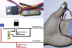
Next, connect the end of the white wire to the beginning of the blue. Plus USB connector will be connected to this spike. The beginning of the white wire through the resistor (it must be installed, otherwise the transistor will heat up, and the transformer will whistle and nothing will work) is connected to the base of the transistor. By the way, the pinout of the transistor, if you look at it not from the side of the cut, the emitter base is the collector. We connect the collector to the end of the blue wire. Later, a minus from the USB connector will be connected to the emitter. The LED strip is connected with a plus to the collector and a minus to the emitter. The device of this home-made lighting device is simple and clear, so I don’t attach the diagram.


All the nuances are visible and understandable from the photo. Other rantings about the design of this homemade product - laptop keyboard backlight out of place. Everyone will work out the design and construction for himself. based on available materials. Don't limit your imagination.
Very often, people working at a computer, and just spending their free time on it, are faced with such a problem that in order to type any text or message, you have to strain your eyes. At the same time, the lamp standing on the computer table shines from the monitor, and it is not clear how to make a backlit keyboard. With all this, the main lighting of the room is also blocked by the person sitting at the table.
So is there a way out of this situation? As it turned out - yes.
Do-it-yourself keyboard backlighting, and with a minimum of costs, may well become such an output. After all, it is always interesting to create something yourself, at home.
You need to understand whether it is difficult to make a backlight for a laptop or a backlit keyboard for a desktop computer. How much time and effort will be spent on it?
There are several options for making such a backlight with your own hands, both simple, accessible to a person who has never encountered such work in his life, and more complex, the manufacture of which requires knowledge of both computer technology and radio electronics. But you should probably start with simpler ways.
Simple keyboard backlight
To make such a backlight you will need:
- LED strip 64 cm long;
- power button (with fixing);
- battery connector "Krona";
- the battery itself
- Matchbox.
You should not buy a Chinese-made battery, because the powered backlight on such a Krona will not work even a day. LED strip should be a density of 60 or 120 elements per meter.
The first step is to tin the ends of the wires and the button contacts. One of the connector wires must be soldered to the LED strip. The second through a gap with a button - to another wire of the light strip.
The main thing in this work is not to confuse the polarity on the connector and the tape. Soldered contacts, of course, are isolated, the resulting product is checked, and if everything is assembled correctly, the backlight should work. After that, "Krona" is hidden in a matchbox.
After all the work done, it is necessary to remove the protective film from the LED strip and glue it along the edge of the table with the elements down along the keyboard drawer. Also, a matchbox with a battery is attached to the bottom with superglue or double-sided tape. In this case, the button should be at hand.
The result will be a backlight similar to the photo above.
Laptop keyboard option
Such a homemade device can be useful for those who like to be alone in a dark room with a laptop. The main thing here is to understand how to make the keyboard backlight on a laptop with your own hands, and the work will already go like clockwork.
The fact is that you can’t put a laptop on a sliding shelf, and if it does, then the backlight discussed above will be completely useless. The light from it still does not fall on the keyboard. Well, making a more complex system by disassembling a laptop to install LEDs under the buttons is not at all handy, and therefore you need to consider the option that will get a USB backlight for the keyboard, which is mounted on top of the monitor near the WEB camera.

To begin with, you will need to solder the LED elements in series with the expectation that the backlight will be powered via USB, which means that the voltage that should be equal to when choosing the power and quantity will be approximately 5 volts. The main thing is not to reverse the polarity of the LEDs when soldering. It is advisable to take the resistor included in the circuit with a variable resistance, with its help it will be possible to adjust the brightness of the backlight.
Even a piece of a small plastic bottle can be taken as the basis for the backlight - here you can already be guided by your own imagination. It is better to place the LEDs soldered according to the scheme (below) with a fan, for a diffused, but necessarily directed downward light flux for more optimal do-it-yourself keyboard illumination.
Well, in the end, you need to connect the power to the USB cable. Even if there is no tester at hand, and it is impossible to check which of the wires is "plus" or "minus", it does not matter. You can really find out everything using the “scientific poke” method, connecting in turn the wires coming from the USB connector to the ends of the serially soldered LEDs. And now the USB backlight of the laptop keyboard, made by hand and at home, is ready. You can be proud of yourself, because such a homemade product illuminates every key.
 Assembly diagram of LEDs for backlighting a laptop keyboard
 Option #3 - USB flashlight
This is the simplest version of how to make a backlight on the keyboard with your own hands. For its implementation, you will need a bending metal corrugated part from a piezoelectric home lighter or a guide from a headphone microphone, which will do the same job perfectly. You will also need a USB connector, an LED (by the way, you can solder it out of an old laser mouse) and a few pieces of wire.
Everything is extremely simple - you need to solder the LED to the wires, pass them through the corrugated part of the lighter or microphone, and at the output solder as tightly as possible to the USB connector, naturally, defining the power outputs.
Such a flashlight will shine incredibly brightly, and you can direct it as you like thanks to the corrugated base.
In general, it is quite possible to figure out how to make the backlight of the keyboard yourself, you just need to want, well, and dig deeper into electronic spare parts, which may well be found in any home.
And besides, such an experience that will come along with an understanding of how to make a keyboard backlight with your own hands is very interesting and exciting - a completely different feeling than if such little things were bought in a store.
A useful homemade product that will definitely come in handy almost anywhere where there is a USB:
- At home for illumination: you can connect even to a computer, even to a laptop.
- Hiking, fishing or hunting: you can connect to an external battery (power bank) and lighting in a tent or on the street is ready!
- In the car for lighting: now every radio has a USB input. If you make the wire longer, then you can generally use it as a mobile examination lamp.
- There are quite a few other uses as well.


- USB cable from any unnecessary charging.
- A pair of 5-500 ohm resistors - the resistance depends on the brightness of the LEDs.
- Non-working 220 V LED bulb.


Let's disassemble the light bulb. To do this, pry off the white dome with a flat screwdriver. It is glued on and should gradually move away from your pressure.


We remove the internal board, we will no longer need it, we will have our own.

We make a hole in the base for the wire with a hot soldering iron. You can just drill through.

We skip the wire to power the light bulb.

We now need to assemble a very simple circuit to power the LEDs from USB - 5V.

We do everything on a piece of plastic. My brightness is low, but if you want to be brighter, you need to do everything on an aluminum piece of metal. For better heat dissipation from LEDs. The resistance of the resistors can also regulate the power of the glow of the LEDs, and hence their heating.

We glue our assembled board to the light bulb. Glue on hot glue.

Now we collect the light bulb. Glass can be glued with super glue.

Here's what the finished USB-powered lamp looks like.

And here's how to glow. Almost like the lights before when it worked from 220 V. LEDs can be taken more powerful and more in quantity. But in this case, the current consumption will also increase, which may affect the USB load. I made the best choice.
In this article, we present to your attention an overview of the most interesting idea for making a USB backlight for a laptop keyboard.
We will need:
- glue gun;
- soldering iron;
- USB plug;
- cap from a plastic bottle;
- tester;
- Light-emitting diode;
- 100 ohm resistor.
First of all, we take a tester and determine which resistor is right for us to make the backlight.

Take a USB plug. The first and fourth pins of the plug are positive and negative. The second and third pins are for data transfer. Let's start assembling.

Solder the resistor to the negative terminal. The polarity of the resistor does not matter in this case.


Let's move on to the LED. The plus side of the LED is called the anode, and the minus side is called the cathode. On newer LEDs, the anode leg is longer than the cathode leg. If you are using an LED that was previously used, then the polarity can be distinguished by the sawn off skirt or crystal bed that is located on the cathode.

Solder the minus of the LED to the resistor.


We solder the positive leg of the LED to the positive contact of the USB plug.


We insert the plug into the connector and check the assembly for operability.

We put a mark on the plug, bend the resistor and the LED to the desired position, fill the cap from the plastic bottle with hot glue and immerse the resistor with the LED bulb and the plug to the mark.


The backlight itself is ready. If desired, you can paint it with spray paint.
Connecting LEDs to usb and other computer connectors
The use of LEDs in modding is very popular, due to the low complexity of their connection and the good visual effect obtained from their use. It is for this reason that a practical guide for connecting LEDs in a computer is offered to your attention. This guide is aimed at modders who are just starting to use LEDs in their modding projects and in it I will talk about three of the most popular ways power connections to the LEDs, depending on the connector: from 4-pin molex, from 3-pin or from USB.
Necessary: To accomplish this LED connection guide we will need the following things:
- LEDs. Everything is clear here, in fact, we will connect them.)
- Resistors. Required to reduce the voltage and current from the power source to the values required by the connected LED.
- Connectors. They will connect the LEDs to the power sources in the computer.
- Soldering iron with everything you need for soldering.
- Heat-shrink tubing. It will be needed to ensure a neat appearance and safety of the soldered joint.
- multimeter(tester). For checking voltages and continuity of connections.
- Nippers and/or blade. For stripping and working with wires.

 As can be seen from the list above, we will not need any complex, expensive or tricky devices to complete this guide. And the operation itself for connecting LEDs is also not particularly difficult. Go to detailed a description of the various ways to connect LEDs in a computer. Connecting an LED to a 4-pin molex4-pin connector molex is one of the most common power connectors in a computer. It was with the help of molex connectors that earlier (and even now in older models) power was connected to hard drives and optical drives. Also, with the help of molex connectors, part of the fans and most computer accessories are connected, such as control panels, backlights, and similar devices. As its name suggests, 4 pin molex contains four contacts: + 12
B (usually a yellow wire), + 5
B (usually it is a red wire), as well as two ground contacts (black wires). Accordingly, when connecting an LED to a 4-pin molex, you have the opportunity to choose exactly where to connect the LEDs, namely to 12 or 5 volts.
As can be seen from the list above, we will not need any complex, expensive or tricky devices to complete this guide. And the operation itself for connecting LEDs is also not particularly difficult. Go to detailed a description of the various ways to connect LEDs in a computer. Connecting an LED to a 4-pin molex4-pin connector molex is one of the most common power connectors in a computer. It was with the help of molex connectors that earlier (and even now in older models) power was connected to hard drives and optical drives. Also, with the help of molex connectors, part of the fans and most computer accessories are connected, such as control panels, backlights, and similar devices. As its name suggests, 4 pin molex contains four contacts: + 12
B (usually a yellow wire), + 5
B (usually it is a red wire), as well as two ground contacts (black wires). Accordingly, when connecting an LED to a 4-pin molex, you have the opportunity to choose exactly where to connect the LEDs, namely to 12 or 5 volts.
 In our case, I will connect a four-chip 10mm green LED which works from 3.2 volts and consumes 80 mA to 12 volt source. We need a resistor with a resistance of 120
Ohm. Connector itself 4 pin molex you can either buy it separately, or use a connector taken from something old / unnecessary device, such as an extension cord, splitter or adapter.
In our case, I will connect a four-chip 10mm green LED which works from 3.2 volts and consumes 80 mA to 12 volt source. We need a resistor with a resistance of 120
Ohm. Connector itself 4 pin molex you can either buy it separately, or use a connector taken from something old / unnecessary device, such as an extension cord, splitter or adapter.
 Before connecting the LED, it is advisable to first check with a multimeter the compliance of the selected contacts, as well as determine where the LED has positive (plus) and negative (minus) contacts. After that, it is necessary to strip the wires that come from the molex connector and solder a resistor to the positive contact, remembering to close the soldered connection with a heat shrink tube. After that, it is necessary to solder the positive contact of the LED to the other contact of the resistor, also covering the place of soldering with heat shrink. The negative contact of the LED is soldered to the "ground" contact of the molex connector, the soldering point is once again closed with a heat shrink tube. Now everything is ready and you can safely connect the LED to power to check its performance. We check - everything works!


 Connecting an LED to a 3-pin connector
Connector 3-pin is a standard connector for connecting fans in a computer and quite often they remain superfluous, so you can connect an LED to them. This is sometimes done when installing water blocks with transparent covers on the processor, because there is no longer a need to connect the processor cooler fan, and you don’t want to pull the wire to connect the LED from somewhere far away - you can use the 3-pin connector. The described method of connecting LEDs is practiced, for example, by Thermaltake with its processor water blocks, which have a transparent cover. As its name suggests, a 3-pin connector has three pins: + 12 V, ground, as well as the third pin, which is the contact of the fan speed sensor.
 In our case, to the connector 3-pin I will connect a 10mm red LED, which operates from 2.3 volts and draws 50 mA to a 12 volt source. To connect an LED- we need a resistor with a resistance of 220 O m. As you should already understand, to connect the LED, we will use two contacts, namely +12 V and ground. It is worth remembering that 3-pin connectors are designed for connecting fans, so they are better. do not load too much, however, a few watts of additional load will not create a problem, and for LEDs they will be enough with a margin. 3-pin connectors can either be purchased or use a connector taken from some old/junk device such as a fan, extension cable, adapter or splitter.
 Before connecting the LED to the connector 3-pin it is advisable to additionally pre-check with a multimeter the correspondence of the selected contacts, as well as determine where the LED has positive (plus) and negative (minus) contacts. Now you need to strip the wires that come from the 3-pin connector and solder a resistor to the positive terminal, covering the soldered connection with heat shrink tubing for better appearance and safety. It is necessary to solder the positive contact of the LED to the second contact of the resistor and also close the place of soldering with heat shrink. The negative contact of the LED is soldered to the "ground" contact of the 3-pin connector, and once again the soldering point is closed with heat shrink tubing. Now everything is ready, you can safely connect the 3-pin connector to the power supply to check the operation of the LED. We check - everything works as expected!


 Connecting an LED to a USB Connector
For those who do not know, USB is a data transfer interface for peripheral devices, however, in addition to the data in the USB connector, it also transmits voltage to power various devices. To be precise, there are four pins in the USB connector: two pins are responsible for data transfer and two more for power. A 5 V voltage supply with a current of up to 500 mA is available in the USB connector. USB connectors are rarely sold separately, so the easiest way is to buy a USB cable or take a cable you don't need from some device. Full-sized USB connectors come in two types that differ in size: USB type A - 4 x 12 mm USB type B - 7 x 8 mm All differences are only in shape, in terms of available pins they are the same. In my case, I used a USB extension cable with USB type A connectors.