Turning eccentrics on a lathe. Work on screw-cutting lathes. Trimming ends and ledges
Eccentric (misaligned) are parts in which the axes of individual surfaces are offset, but parallel to the axes of other surfaces. These parts include eccentric cams (the axis of the hole does not coincide with the axis of the disk - Fig. 309, a, b), eccentric rollers (the trunnion axis is offset from the axis of the shaft - Fig. 310), crankshafts (axes of connecting rod journals
Displaced relative to the axes of the main journals - fig. 311).
Machining of eccentric cams. There are two ways of processing eccentric cams: at the first, a hole is drilled after processing the outer surface of the disk, at the second, a hole is first processed, then, based on it, the outer surface is processed.
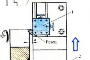
First way. The pre-turned disk is clamped in a four-jaw chuck (Fig. 312) with the center 0 position aligned with the thickness gauge. Then the cartridge is placed so that its cams are located horizontally, a cutter or a metal rod fixed in the tool holder is brought to the workpiece. According to the limb of the transverse support, a division is noticed corresponding to the contact of the rod with the workpiece. With the handle of the transverse caliper, the rod is pulled towards itself by the amount of eccentricity e (the play between the screw and the caliper nut must be selected). Then the cams are displaced until the workpiece contacts the rod. Contact (clamp) is controlled by a piece of paper pinched between the rod and the workpiece; The paper should come out with little resistance. Now the center of the eccentric hole 02 will be against the axis of the spindle and the eccentricity e will be maintained: you can drill and bore (or ream) the hole.
More precisely (with an accuracy of 0.01 mm), the control of the displacement of the cams during the processing of eccentrics of parts is carried out by an indicator fixed in the tool holder.
The second way. The disc is mounted with a pre-machined hole on a mandrel, which is fixed in a four-jaw chuck, and shifted to eccentricity e in the manner described above. Machining on center mandrels is also possible (Fig. 313). With pre-drilled offset holes, the mandrel is installed at the centers of the machine. Processing of eccentric rollers. Short* eccentric pins (offset trunnions) are machined in a four-jaw offset chuck as described above. Long eccentric rollers are machined in centers. The center holes at the ends of the rollers are pre-drilled on a drilling machine by marking or using special devices. First, the shaft is installed on the center holes A, corresponding to the axis of the shaft, and the main (main) necks are machined. Then the shaft is installed in the center on the offset center holes £> 1 II2 And the eccentric necks are turned (see Fig. 311).
Processing of crankshafts. If the axis of the eccentric neck goes beyond the crankshaft blank, then to process this neck, the workpiece is installed in the center
Spacious washer (Fig. 314). Centrifugal washers 2 and 3 are mounted on the main journals of the shaft. At the ends of the centrifugal washers, center holes are drilled with a given offset e from the axis of the main journals. When processing eccentric necks, the workpiece is installed in the centers on the offset center holes of the washers. Spacers 5 serve to increase the rigidity of the workpiece. Counterweights 4, 6 balance the displaced parts of the workpiece. As the turning progresses, the weight of the workpiece decreases and the counterweights are replaced with lighter ones.
TO USE THE REAR TOOL HOLDER TO FACE THE DISC:

1 - rear tool holder, 2 - cross slide of the support, 3 - front tool holder for cutting the end face of the disk. R<-зеи, закрепленный в переднем резцедержателе 3, выполняет подрезание, начиная от наружной поверхности до середині»! торца, а резец, закрепленный в заднем резцедержателе 1, осуществляет подрезание отверстия также до середины торца. Путь прохода инструмента в два раза меньше ширины торцовой поверхности заготовки, что сокращает время на обработку торца в два раза. Чистовой проход выполняется одним резцом. На рис. 329 показана схема наладки станка на обработку ступенчатого валика с применением заднего резцедержателя в сочетании с многорезцовой наладкой. Резцы 1 и 2, закрепленные в переднем резцедержателе, производят наружную обточку ступеней, а резцы, закрепленные в заднем резцедержателе, совершают только поперечную подачу и служат для снятия фасок (резцы 3, 5) и для прорезания канавки (резец 4).
Machine tools 1K62, 16K20 and 1P611GІ are supplied with rear tool holders. Machines of old designs can be
It is possible to carry out multi-cutting adjustment of the machine without the manufacture of special equipment, using a conventional tool holder for this. The use of a rear (additional) tool holder allows you to speed up a number of turning operations: simultaneously carry out external and internal processing; longitudinal turning with incisors located in front and behind; threading using the reverse stroke of the caliper; grooving and chamfering, etc. In fig. 328 shows the use of the rear tool post
Mi longitudinal and transverse movement carry out the adjusting movement of the cutter.
The combination of multi-tool setting of the front tool post using
332 DEVICE IN K. SEMINSKY FOR BORING INTERNAL SPHERES:
1 - spring, 2 - rack, S - gear-, 4 - housing, 5 - strap
The rear tool post nib provides a dramatic increase in productivity.
Adjustment of one-sided installation of cutters "in front" is also effective. Adjustment (Fig. 331, a) allows cutters / and 2 to grind steps (feed from left to right), cut a groove with cutter 2, and cut the end with cutter 3 and chamfer. The cutters are fixed in an additional tool holder. In the setup shown in Fig. 331, b, two cutters are used: boring 4 and thrust 5. An important means of reducing processing time is the use of various machine tools.
The experience of an innovator turner, laureate of the State Prize, Honored Inventor of the Ukrainian SSR V.K. 332 and 333 Seminsky's devices for processing internal spherical (spherical) and conical surfaces are shown.
333 DEVICE V. K - SEMINSKY FOR MACHINING CONIC SURFACES WITH AUTOMATIC SUPPLY OF THE TOP CALIPER:
334 PARTS PRODUCED BY PROCESSING ON LATHES.
Lathes include a large group of machines designed mainly for processing surfaces of revolution coaxial to the spindle axis (cylindrical, conical, shaped, screw, and also face). For processing the outer surfaces of parts such as shafts, both center and centerless lathes are used. Concentric surfaces of parts such as bushings and rings are machined on center turning and chuck lathes. Parts such as disks (with significant end surfaces) are machined on frontal lathes, which occupy a smaller area than center machines and are better suited for processing the outer and inner end surfaces of the part. Face lathes have devices for maintaining a constant cutting speed, as well as devices for cutting face threads (spirals).
Machining on centerless lathes is carried out by rotating multi-cutting heads with longitudinal feed of workpieces. On these machines, pipes are turned, long products of a cylindrical shape. The machines are characterized by high productivity; they belong to the group of special machines. Widely used in the industry universal lathes chuck-center horizontal layout.
Ways to install and align workpieces. The most commonly used mounting and alignment methods for workpieces are listed below. Workpiece positioning error see chap. 1.
Installation on centers most often used for shafts, drums, cylinders, as well as various workpieces mounted on mandrels. Small and medium-sized workpieces are mounted on solid thrust centers (Fig. 1a). In the case of trimming the end of the workpiece from the side of the tailstock, a half-center is used. Rear centers when processing at high cutting speeds are rotating (weight of parts up to 20 tons). The installation accuracy on such centers is lower than on solid ones (radial runout is allowed up to 0.007 and 0.015 mm, respectively, for centers of increased and ordinary accuracy). Blanks with a hole are installed on centers of increased diameter with a cut off top of the cone (fungal centers). On fig. 1, b, the rear center is fungal rotating, the front center is corrugated. The use of a corrugated center (trihedral or multi-toothed) allows you to completely process a smooth shaft or cylinder along the outer surface and cut both ends of the workpiece, since processing is carried out without a leash. However, installation on grooved centers does not provide high accuracy (radial runout up to 0.5 mm), it allows only a single use of the base due to its damage during the first installation.
Workpieces of small diameter are mounted on reverse centers (Fig. 1, c), while using conical chamfers on the outer surface. Transmission of torque during the finishing of such workpieces is possible without a driver. The processing of cones by the method of shifting the tailstock is carried out with installation on ball centers (Fig. 1, d).
Mounting on a floating front center (Fig. 1,e) with the workpiece based on the end provides high dimensional accuracy along the axis (with the method of automatically obtaining dimensions). To reduce the vibration of the system, the center is locked manually with a screw 1 or automatically - when the center is jammed with plungers 2 (Fig. 1, f). The presence of a drive washer 3 in the design allows processing the workpiece in one setting, since there is no need to use a drive device. This scheme is used when processing workpieces with a diameter of up to 80 mm, a length of up to 400 mm. When roughing, the washer is made with a three-toothed one (Fig. 1, g), when finishing, it is multi-toothed (Fig. 1, h). In the latter case, smaller traces remain from the teeth of the driving device at the end of the part. Workpieces with a large diameter hole are installed on the centers using plugs or crosses (Fig. 1, and - n). Corks are made whole for D = 10 ÷ 150 mm (Fig. 1, j) expanding for D = 40 ÷ 350 mm (Fig. 1, l), self-expanding for D = 70 ÷ 450 mm (Fig. 1i). Adjustable crosses are used when D = 400 ÷ 1500 mm (Fig. 1, m); at D >1500 mm, welded crosses are used (Fig. 1, h).
Installation on plugs is performed without alignment with an accuracy of 0.03-0.10 mm, on welded crosses - with an accuracy of 0.2 mm. If the workpiece is mounted on adjustable crosses, the radial runout and the position of the part in the horizontal and vertical planes are controlled with an accuracy of 0.5 mm.
Mounting in the chuck and on the rear center used in the case of processing workpieces of large diameter and length, in the absence of a center hole on the side of the headstock. Installation accuracy in self-centering cartridges 0.05-0.10 mm; when using four-cam chuck installation is performed with alignment of the position of the workpiece from the side of the chuck in height and runout with an accuracy of 0.05 mm.
Installation in the chuck and on the fixed rest used to process the hole and the end of the workpiece, as well as the section of the workpiece located between the steady rest and the cartridge.
When processing heavy workpieces, open-type steady rests are used, in other cases, closed-type ones. Under the steady rests, special belts are machined (Fig. 2, a). In some cases, shafts with a diameter of 30-200 mm can be installed without processing the belts using adjustable couplings (Fig. 2, b). The installation of blanks is carried out with the alignment of the position in the horizontal and vertical planes and the runout with an accuracy of 0.03 - 0.05 mm. Without alignment, workpieces are installed in special cartridges (Fig. 2, c).
Mounting on centers using steady rest used in the processing of non-rigid workpieces (Fig. 3). The mounting surface under the steady rest is subject to high requirements for total deviations and tolerances of the shape and location of the surfaces.
When installed in cartridges workpieces of small length are processed. The greatest rigidity of the system is provided when the workpiece is fastened to the outer or inner surface of the rim (crown), and the smallest - when fastened to the hub. Installation in self-centering cartridges is carried out without alignment with an accuracy of 0.1 mm; in a split sleeve or non-hardened cams - 0.03 mm; V four-cam chucks with alignment on the outer diameter and end - with an accuracy of 0.05 mm.
Workpieces with a hole for high demands on the location of bases and work surfaces mounted on end or center mandrels. Smooth mandrels with a gap are used (Fig. 4, a), conical (Fig. 4, b), cam (Fig. 4, c), ball (Fig. 4, d), roller self-jamming (Fig. 4, e), collet (Fig. 4, f), with disc springs (Fig. 4, g), with hydroplastic (Fig. 4, h), elastic elements of the corrugated type (Fig. 4, i), with an interference fit (Fig. 4, k ) etc.
On the cam mandrel (see Fig. 4, c), the workpiece is fixed with several cams 1, which, when the mandrel is installed on the centers, are spread apart with fingers 2. To fix the workpiece on the ball mandrel (Fig. 4, d), the separator with balls must be shifted along the axis to the left. In this case, the balls are wedged between the workpiece and the sleeve 1. The roller mandrel (Fig. 4, e) is self-jamming. At the initial moment of processing, the workpiece rotates somewhat relative to body 1; rollers 2 are wedged between the surface of the hole and the flats of the body. On mandrels with elastic elements (Fig. 4, e - i), the workpiece is installed with a gap, then the elastic element is deformed, with the help of which the gap is eliminated.
An interference mandrel (Fig. 4, j) makes it possible to process the outer surface and ends of the workpiece in one set-up, as a result of which a high accuracy of the location of the surfaces is ensured. On such mandrels, gears are often machined before gearing. When pressing the workpiece onto the mandrel, it is necessary to accurately maintain the size L . To facilitate installation, the mandrel has a guide part 1 with a guide key 2. Mandrels of this type are also used to install workpieces with a smooth and splined hole. Mandrels with tension and mandrels with elastic elements provide the highest accuracy in the location of surfaces.
Details of complex shape (levers, body parts) when machining on lathes mounted on a faceplate. The correctness of the installation is checked by aligning the position of the cylindrical surfaces, the end and the plane of the connector. To reduce vibration, a balancer is used.
Angle installation used in the processing of body parts, bearings, etc. The workpiece is fixed in special fixtures (Fig. 5) without alignment (installation accuracy 0.1 mm) or on a universal square with alignment according to marking or previously processed surfaces and the parting plane - installation accuracy 0.5 mm. Mounting on a square is often used when processing a system of coaxial holes of different diameters in body parts on CNC machines. By shifting the cutter along the radius, you can obtain the specified hole sizes. On CNC boring machines, this is more difficult to do.
In the absence of boring machines, heavy unbalanced body parts are machined on lathes with the installation of the workpiece on the caliper; the tool is mounted in the spindle with additional support on the tailstock.
When aligning cylindrical workpieces, installed in three and four-cam cartridges, check the runout of the workpiece (with a large length, the runout is checked at the chuck and at the free end) (Fig. 6, a) and the correct location of it in the horizontal and vertical planes. In this case, the control tool is fixed on the support or on the machine bed. The correct position of the rectangular workpiece is provided by the following methods. In the first method (Fig. 6, b), the workpiece is sent for turning with marking risks applied on the end, located at a distance of a and b from the edges. When installing the workpiece, the intersection point of the marks must be aligned with the axis of rotation. To do this, measure the distance from the horizontally located risk (for example, a) to the guides or caliper. After two measurements (at the initial position and after turning the chuck by 180°), the necessary displacement of the workpiece is determined. By loosening one and tightening the opposite cam, the workpiece is shifted to the desired position.
In the second method, to speed up the installation, the intersection point of the marks is coreded, the workpiece is pressed by the center, and then the cams are carefully brought up.
To align the position of composite blanks, mark the position of the diametral plane, and then check the position of the joint with an indicator (they achieve a horizontal position of the joint plane and align it with the axis of rotation).
When mounted in a chuck and steady rest control the runout of the workpiece at the chuck. Then check the position of the shaft near the steady rest by the following methods. If there is a center hole, the position of the workpiece is checked by the annular gap between the hole and the center using a feeler gauge (Fig. 7, d). The misalignment of the quill of the rear beam or the axial tool is controlled by a tool mounted on the quill or on the workpiece (Fig. 7, a).
The correctness of the position in the vertical and horizontal planes is assessed by the gap between the thickness gauge needle and the surface of the workpiece (Fig. 7, b), using indicators. Indicators can be mounted on a special device (Fig. 7, c). The readings of the indicators are corrected taking into account the actual diameter of the workpiece at the place of control. Some workpieces after alignment (rotors of turbines, generators, etc.) are finally installed according to the method, the scheme of which is shown in fig. 7, c. The misalignment with the control band bored in the steady rest is controlled by measuring the distance from this band to the surface of the workpiece at three points.
Schemes for performing basic operations. Turning with one cutter- the main method of processing on lathes. The overhang of the cutter is taken no more than 1.0-1.5 of the height of its rod, respectively, for cutters with plates made of hard alloy and high-speed steel. The top of the cutter is set at the height of the centers or slightly higher (rough turning) or lower (finish turning). At R > 50 mm displacement is carried out by the value h ≤ 0.01 R (where R - workpiece radius). When finishing, such an installation protects against possible marriage due to deformation of the cutter. The position of the tip of the cutter is checked by the risk applied to the quills of the tailstock, in the center or using special templates. Adjusting the tool for size by diameter is carried out by the method of test moves. A batch of blanks is processed by the method of automatically obtaining dimensions without shifting the cutter in the transverse direction along the limb, using indicator and hard stops.
When processing stepped workpieces, rotary multi-position stops are used in combination with measuring tiles (Fig. 8, a). The longitudinal dimensions are maintained along the limb, according to the risks marked earlier, along the stops (the stops can be rigid, rigid with tiles, drum and indicator ones) (Fig. 8, b). Turning using multi-cutter setup allows you to reduce the processing time of a batch of parts.
End machining with one cutter . When processing workpieces fixed in the chuck, through-cutting cutters are used. The use of scoring cutters when removing large allowances with a feed to the center leads to the formation of concavity. Therefore, the finishing of the ends is carried out with the feed of the cutter from the center to the periphery. With the same feed, the ends of large workpieces are processed, since as a result of wear of the cutter, a deviation, which is less dangerous when assembling parts, is formed - concavity.
Hole machining with an axial cutting tool . The tool (drill, countersink, reamer) is mounted in the tailstock or caliper. Drilling with a twist drill is carried out atl/d < 10. Инструментом для глубокого сверления (рис. 9) обрабатывают отверстия с отношением l/d > 10. Holes of considerable length are machined with “reverse feed” to reduce vibrations and improve accuracy (the mandrel works with tension).
Machining holes with a boring cutter. holes d<70 мм, l < 150 мм при l/d <5 обрабатывают резцом, закрепленным в суппорте (рис. 10,а); при d > 70 mm, l> 150 mm, l/d < 5 - резцом, закрепленным в расточной оправке (рис. 10,б); при l/d > 5 install an additional support in the spindle (Fig. 10, c); atl/d > 10, boring heads with guide blocks are used (Fig. 10, d). Closed holes, such as roll chambers, are machined with special tools. After inserting the tool into the hole, the tip of the cutter is set to the working position by a lever or other mechanism.
Drilling a hole with an abrasive tool. Using special tools, the holes are processed by internal grinding (Fig. 11), superfinishing, honing.
cutting through grooving and parting . Single cutter machining is the main method for machining simple grooves and parting off parts. The cutters are set strictly according to the height of the centers, without skew to the axis of the workpiece. Narrow (up to 20 mm wide) grooves of low accuracy are cut in one stroke, more accurate grooves in three strokes. Wide grooves of low accuracy are cut immediately in several working strokes; for high-precision grooves, the side walls are finished after roughing. Irresponsible shaped grooves are cut in one working move. In other cases, the processing is carried out first with a slotted cutter, and then with a shaped cutter. Thin-walled parts are cut with a straight cutter, thick-walled and shafts are cut with a bent cutter. Using a special setup (fig. 12), you can cut off several parts or cut both the outer and inner grooves on the part at the same time.
Processing of conical surfaces. A shaped cutter is used to process short outer and inner cones. Processing can be carried out with longitudinal and transverse feeds. With high requirements for accuracy, the tool is installed according to the template, taking into account the deformation of the system.
Internal cones (centering chamfers) with d < 1000 мм и конические отверстия обрабатывают специальными зенковками, зенкерами и развертками, Стандартизованные конусные отверстия (в насадных инструментах и т. п.) обрабатывают комплектом разверток после сверления (диаметр сверла на 0,5- 1,0 мм меньше номинального размера первой развертки). При обработке с поворотом верхних салазок суппорта наибольшая длина конуса ограничена, так как определяется ходом верхних салазок суппорта.
By the method of shifting the tailstock, gentle outer cones of low accuracy are processed. The method is simple, as it does not require special equipment. During processing, the center seat is crushed, so it is better to use a ball center for installation. The necessary displacement of the tailstock (usually by no more than 0.01 of the length of the conical surface of the workpiece) is set according to the scale printed on this headstock, according to the indicator or the limb of the caliper (when controlled using a probe and a bar fixed in the caliper).
Cones with an angle of inclination up to 12 ° are processed along the conical ruler. The method provides higher accuracy compared to the previous one. Machining on a copier using electric or hydraulic devices, compared with machining on a conical ruler, provides greater accuracy and less wear on the copier. Reverse taper not more than 30-40°. With the help of a transverse feed guitar, the cutter is given simultaneous longitudinal and transverse feeds.Me todobtaining a cone with simultaneous axial and radial feeds is widely used on CNC machines.
Processing of shaped surfaces . Shaped cutters process surfaces up to 60 mm long (on large machines up to 150 mm long) and transitional surfaces with a radius of up to 20 mm. Roughing to increase productivity is carried out with conventional cutters. When using rotary devices, the tip of the cutter moves through an angle α along an arc of a circle with a radius R , while processing the spherical outer (Fig. 13, a) and inner surfaces (Fig. 13, b) or barrel-shaped profile (Fig. 13, c) of the workpiece. The cutter is usually moved using a worm gear (Fig. 13, d).
Spherical surfaces of medium-sized workpieces are processed using lever devices of various designs. For example, one lever support is fixed on the frame (Fig. 14), the other on the caliper. When the caliper is fed to the axis, the cutter moves along the radius R , processing a spherical surface.
When processing on a copier, direct action devices are used (the cutting force acts on the copier; wear and elastic deformations of the copier are large, processing accuracy is low) and devices with a reinforcing element. In direct action devices, the copier is installed coaxially with the part, mounted on the tailstock using a bracket at the back or front (Fig. 15, a) of the machine. In this case, the roller is pressed against the copier with different force (Fig. 15, b). When finishing, apply the scheme II , for light work - a diagram I , when roughing for heavy work - a diagram III . In the most accurate devices, a knife probe is used instead of a roller. For processing surfaces with profile elevation angles of more than 35 °, stretched copy rulers are used. With the help of a special mechanism, such a ruler moves relative to the probe at a higher speed, which makes it possible to make the elevation angles on the ruler smaller than on the part.
With the help of a hydraulic support, it is possible to process surfaces with increasing and decreasing diameters, but no more than D - d≤ l, Where l- the length of the treated area. The use of a hydraulic support provides an increase in productivity by 1.5-2 times.
Special cup tools process spherical internal (Fig. 16, a) and external (Fig. 16, b - d) surfaces with a radius R , The tool spindle is set at an angle α :
where D - diameter of the cup tool; b - the distance between the top of the tool and the center of the sphere. The tool rotates during processing from a special drive.
Machining of cams, curvilinear grooves. On a copier installed coaxially with the part, cams of small length are processed. Lever fixture (Fig. 17, a) is used for profile dropsRmax - Rmin≤ 0,5 Rmin, but not more than 150 mm. The spiral grooves are processed in the same way.
When making a cam according to a copier and a machined surface, a copier of small thickness is attached to the end of the workpiece (Fig. 17, b). A small initial section is processed along it; then the roller moves along the previously processed surface area. This method is used when processing smooth cams with a differenceRmax - Rmin≤ 0,2 Rminbut not more than 100 mm. Processing accuracy is low.
Processing of eccentric surfaces. With an eccentricity of more than 8-10 mm, offset center holes are drilled in shafts with eccentrics (Fig. 18, a) along the markings or the conductor. Parts with holes are mounted on mandrels (Fig. 18, b). For large eccentricities, use centrifuges(yokes): for D \u003d 45 ÷ 860 mm - solid (Fig. 18, c), for D - 55÷250 mm - detachable (Fig. 18, d). When mounted on cantilever mandrels, processing is performed without alignment. The accuracy of processing depends on the error in basing the part on the mandrel (Fig. 18, e).
Offset workpiece position in use four-cam cartridge (Fig. 19, a) is controlled with an accuracy of 0.05 mm (on a cleanly machined surface). When using three-jaw chucks (Fig. 19, b), the thickness of the measuring plate b = 1.5e, where D - base diameter; e is the eccentricity.
Eccentric surfaces are also processed using special cartridges (Fig. 19, c), consisting of three-cam chuck 1, turntable 2 and caliper 3 to create eccentricity. When installing the part in special rings (Fig. 20), holes are bored, located eccentrically and at an angle to the outer surface. When installing the rings, it is necessary to ensure their correct location (usually, alignment is carried out according to the risk applied on the ends of the rings and forming the part). During processing, the right ring is fixed in the cartridge, the left - on the lunette.
Designing a turning operation. On the machines of the turning group, parts of various shapes and sizes are processed, mainly belonging to the class of bodies of revolution. Among them, parts such as shafts have a length several times greater than the diameter; for parts such as disks, the diameter is greater than the length, and for parts such as bushings, cylinders, the diameter and length are of the same order. The difference in shapes and sizes of parts affects the way the workpieces are installed for processing and the sequence of processing. But at the same time, these details have a lot in common. The unifying feature is that they are formed mainly by external, internal and end surfaces having a common axis of rotation. Therefore, when processing such parts, in addition to the general task of obtaining specified dimensions, there is a technological problem of ensuring the alignment of these surfaces and the exact location of the ends relative to the axis of the part. These requirements are provided by the following methods of setting and processing workpieces on lathes: 1) processing of coaxial surfaces from one installation; 2) processing in two setups - first the outer surfaces, and then the inner ones with the part based on the outer surface (processing from the outer surface); 3) processing in two setups - first the inner surface, and then the outer one based on the inner surface (processing from the hole).
Machining in one setup ensures small deviations from the alignment and perpendicularity of the ends of the axis of the part in the manufacture of high rigidity parts. This also applies to the processing of shafts with installation on centers, although this processing corresponds to the third method. When centering the shaft, holes can also be machined. Reinstalling the shaft does not cause large deviations in the location of the surfaces. The considered second and third methods relate to the processing of parts fixed in the chuck and on the mandrel.
Machining from the outer surface (based on this surface when machining a hole) provides reliable fastening and transmission of high torque. However, the accuracy of the installation of the part in the cartridges along the outer surface is low, since wide tolerances are assigned to the dimensions of the outer surface and the installation error in the cartridge is high. But in some cases, the use of this method is dictated by the peculiarities of the technological process.
If the third method is used (machining from a hole), then the final processing of the part is carried out with its installation on a mandrel, which in many cases provides high accuracy in the location of surfaces (comparable to the accuracy of machining in one setup) and allows the use of simpler and more accurate fixtures (mandrels) . Large parts on mandrels are not processed.
In addition to the methods discussed above, other methods are also possible. So, on CNC machines, processing is performed in two settings. First, the part is machined on one side, then it is rotated 180° and machined on the other side. In this case, surfaces bound by tight tolerances are desirable to machine in one setup.
Forgings, castings, piece blanks from rolled products can be used as blanks during processing on lathes. In automated production, in particular when processing on CNC machines, the use of workpieces with low accuracy is unacceptable. In this case, the tolerances and allowances of workpieces should be 10-30% less than when processing on manual machines.
Shafts must be straightened and heat treated prior to machining to improve machinability and relieve residual stresses. Other parts are also subjected to heat treatment.
The tightening of requirements for the accuracy and material properties of workpieces processed on CNC machines is explained by the need to reduce the load on the machine, the desire to reduce the amount of chips generated during processing, and create the most favorable working conditions for the cutting tool. The machine on which peeling and roughing is carried out requires constant attention of the operator. Consequently, it is impossible to organize multi-machine maintenance and include the machine in flexible production modules and systems.
In some cases, it is advisable to use complex blanks in the manufacture of parts. From a complex workpiece, several parts can be processed, different, but similar in shape and size (Fig. 21).
Rolled stock is often used as a blank (especially in automated production: mass - when processed on automatic and semi-automatic machines and serial - when processed on CNC machines). Rolled products are cut into pieces of measured length on cutting machines: hacksaw, band saw and circular saw. The accuracy of this operation affects the subsequent turning operation. It is necessary that the deviation from the perpendicularity of the end face of the outer surface be minimal. The most productive methods are cutting off rolled products with circular saws and abrasive wheels. The greatest accuracy is ensured when the workpiece being cut is rotated. With a workpiece diameter of more than 50 mm - piece workpiece (for one part); with a smaller diameter, one workpiece can be used for several parts.
After receiving a piece workpiece of a medium-sized shaft, technological bases are processed - two ends and center holes. Center holes and shaft ends are the basis not only for turning, but also for grinding operations, as well as for the repair of parts. Therefore, they are subject to high requirements for coaxiality, constancy of depth, diameter and cone angle. To perform this operation, central, center-cutting, milling-centering, center-cutting machines, as well as universal turning, milling, drilling and other machines are used.
Processing can be carried out with sequential or parallel-sequential execution of transitions. The expediency of performing one or another processing option is determined by a technical and economic calculation. As a rule, the combination of transitions and the use of machines for complex processing in many cases is advisable even with a small load of machines (10% or more). In addition, double-sided machines provide, during processing, a higher accuracy in the location of surfaces (ends and center holes) of technological bases. So, when processing on a two-sided central machine 2910, the deviation from the alignment of the center hole to the outer surface does not exceed 0.072-0.120 mm; the tolerance for the depth of the center hole is 0.18-0.30 mm.
Double-sided center-cutting machines (for example, MP179, 2931, 2932, etc.) also make it possible to turn shaft ends, chamfer, drill and bore holes, and cut threads. The use of equipment of this type significantly affects the subsequent turning - in many cases, the shaft can be machined in one charter, i.e. there is no need to reinstall it, since the outer surface of the extreme necks has already been machined.
If the turning operation is performed on CNC machines, then it is advisable to perform the processing of technological bases on center-cutting machines. In addition, after processing on center-cutting machines, additional trimming of the end face on a lathe is not required (after milling the ends, their trimming on a lathe is mandatory). Tolerance for the length of workpieces before processing on CNC machines - no more than 0.6 mm.
With the subsequent processing of shafts (after heat treatment), the requirements for the accuracy of processing center holes increase. When grinding center holes on special machines (3922P, 3922E, MB -119, etc.) provides a deviation from the roundness of 1 - 3 microns, a deviation from the straightness of the generatrix up to 4-6 microns; surface roughness parameter up to Ra = 0.63 µm.
When fixing a workpiece such as bushings, disks, etc., in the chuck of a CNC machine, often before the main turning operation, technological bases are processed on manual machines. On a CNC machine, workpieces are fixed in chucks using non-hardened cams. To improve the accuracy of the installation, unhardened cams are bored before processing the part according to a special program in two transitions - roughing (Fig. 22, a) and finishing (Fig. 22, b).
The correct choice of technological bases determines the deviation of the location of the surfaces of the workpiece in the working area of the machine, and, consequently, the uniformity of the allowance during processing, the accuracy of processing interconnected surfaces, the rigidity of the workpiece fastening and the productivity of processing.
On chuck-type lathes, workpieces are fixed: in a chuck, on a faceplate, on a square located on a faceplate. The most commonly used automatic (driven) quick-change three-jaw chucks. In this case, the base of the workpiece is the end, cylindrical and conical (at least 8-10 mm long) outer surfaces. Cams can be hardened or unhardened. Hardened cams are used for fastening workpieces with raw surfaces. To clamp stamped blanks or castings with slopes, the working surfaces of the cams can be given a conical shape. In some cases, special cams with oscillating inserts are used to provide contact over a longer length. Non-hardened cams provide high installation accuracy, since the cams themselves are directly machined on the machine before processing a batch of parts, and previously machined surfaces are used on the workpiece.
When choosing the bases and the design of interchangeable jaws, they try to fix the workpiece as close as possible to the chuck and use the cylindrical surface of the largest diameter as the base. However, an end face and a pre-machined inner cylindrical surface are sometimes used. This basing option is less preferable in terms of rigidity and processing accuracy.
Special chucks make it possible to process a workpiece on both sides without changing jaws (Fig. 23).
Special chucks are also used to ensure the processing of reinforcement parts such as crosses from two and four sides with rotation through a certain angle to align the axis of the element being processed with the axis of the spindle. Conventional chucks have relatively short jaw travel.
On machines that are part of flexible production modules, chucks with a large jaw stroke, chucks with quick-change jaw change systems, etc. are used.
The design of a turning operation is part of a more general task of developing a technological process for manufacturing a part (see Chapter 5). It is necessary to know not only in what form the workpiece enters the turning operation, but also what its accuracy should be after processing. The technological development of a turning operation on CNC machines begins with drawing up a sketch of the workpiece in the form that it takes after the previous processing, indicating all dimensions and technical requirements. It is recommended to show on the sketch with thin lines the contour of the part obtained after processing, indicating the tolerances and surface quality.
Despite the fact that before the development of technological processes, the manufacturability of the part is analyzed, when designing a turning operation on CNC machines, it is recommended to additionally analyze its manufacturability. At the same time, attention is drawn to the unification of the elements of the part, the simplification of the geometric shape, and the provision of rigidity during processing.
When using CNC machines, it is necessary to use the technological capabilities of this equipment to the fullest extent. For each machine there is a specific set of tools. You should check the possibility of processing the part using it. If necessary, develop proposals for changing the design of the part.
The greatest effect is achieved when using CNC machines to solve the most complex technological problems, for example, for processing parts of a complex profile, in the case of a high concentration of processing transitions, excluding locksmith work and complex fixtures. On CNC machines, it is impractical to process parts with less than three steps and parts whose setup and alignment time is long. The CNC machine must be busy processing parts of the same name per year for 10-25 hours.
The surface of the part after turning, depending on the purpose and requirements of accuracy, is divided into main and additional sections. The main sections determine the position of this and its associated parts in the product. The accuracy of processing these areas should be the highest. The main areas of the surface are processed with pass-through, copying and boring cutters, additional sections - face and corner grooves, threaded surfaces, grooves for V-belts, etc. are processed with grooves, threaded cutters, etc.
Despite the variety of shapes of parts, it is possible to establish a typical sequence of processing transitions. Usually, the main areas of the surface are processed in several transitions. Transitions can be performed on one machine in one operation if the part is not subjected to intermediate heat treatment, or in several operations on different machines if the part is subjected to heat treatment.
The division of all transitions into separate operations is carried out based on the possible accuracy of surface treatment on a given machine or in the presence of intermediate heat treatment operations.
On CNC lathes, the sequence of processing transitions is as follows: a) preliminary (roughing) processing of the main parts of the surfaces of the part: trimming ends, centering before drilling holes with a diameter of up to 20 mm, drilling (if two drills are used, then first with a drill of a larger diameter), drilling holes , turning (semi-finishing) of external surfaces, and then boring of internal surfaces; b) processing of additional sections of the surfaces of the part (except for the grooves for the exit of the grinding wheel, threads, etc.); in cases where roughing and finishing of internal surfaces are carried out with one cutter, all additional sections are processed after finishing; c) final (finishing) processing of the main parts of the surface of the part, first internal, then external; d) processing of additional sections of the surfaces of the part that do not require roughing: first in the holes or on the ends, then on the outer surface.
The sets of cutting tools used in the processing of the outer surfaces of the part on CNC machines of the turning group are given in Table. 1 and 2. The surface areas of the part processed by this tool are indicated in table. 3. A set of tools for machines 1723FZ, 1734FZ, 1751FZ is shown in fig. 24, and for the 16K20FZ machine, in fig. 25.
Machining on CNC lathes is characterized by the following accuracy. Single surface treatment provides the accuracy of the 12-13th grade and the surface roughness parameterRa = 3.2 µm. The radius at the top of the cutter is assigned according to the smallest radius of the fillet on the part; in other cases, the fillet is performed according to the program. For higher demands on surface quality ( Ra less than 1.6 microns) at the last finishing transition, reduce the feed and increase the speed. At higher requirements (accuracy of 7-9th grade), the final processing is carried out with a finishing cutter with size correction. To ensure high dimensional accuracy during finishing, the cutter is installed in such a plane that the positioning error of the turret head does not affect the dimensional accuracy of the machined surface.
Roughing with the removal of the overlap is carried out in different ways: if the difference in the diameters of the steps is greater than the length of the step, then the processing is carried out with a transverse feed (otherwise, with a longitudinal feed). Modern CNC systems allow this processing to be carried out in a constant cycle. When compiling the program, the initial and required contour are set. The CNC system automatically generates control commands for processing. Schemes of movement of tools during the processing of the main surface areas are shown in fig. 27-29. Usually these areas are processed with roughing and then finishing cutters.
On CNC machines, chamfers, tool exit grooves are processed as indicated above, or when it is most appropriate in relation to tool life and machining productivity. At the same time, it is taken into account that the work of the tip of the cutter during insertion improves if the chamfer is removed. If processing begins with chamfering, then the parts will be burr-free (for the same reason, grooves are often performed after a finishing transition). It is advisable to remove chamfers with the middle of the cutting blade of the tool.
To reduce the complexity of programming, grooves of complex shape are processed according to a typical program with cutters in several transitions (Fig. 30, 31). The final profile of the part is obtained during the finishing transition. The criteria for selecting a machining scheme and tools are the depth of the groove h \u003d 0.5 (D 2 - D 1 ) and groove width B (Fig. 30, a). If h < 5 мм, то предварительную обработку ведут с продольной подачей канавочным резцом при В < 30 мм (рис. 30, б) и проходным резцом при В >30 mm (Fig. 30, c). At h > 5 mm and IN< 30 мм применяют канавочные резцы и работают методом ступенчатого врезания (рис. 30, г). При В < 30 мм после получения канавки шириной до 10 мм (рис. 30, д ) оставшийся материал убирают подрезным резцом (рис. 30, е). Окончательную обработку во всех случаях проводят двумя канавочными резцами по контуру (рис. 30, ж и з ). Аналогично обрабатывают внутренние канавки.
Face grooving shown in fig. 31, a, are as follows. With groove width B = 0.5 ( D2 - D1 ) < 60 мм предварительную обработку ведут по схеме, представленной на рис. 31,б (глубина канавки h < 3 мм), или по схеме на рис. 31, в и г (глубина канавки h > 3 mm). The final processing of the face grooves is carried out with two identical cutters, differing in the position of the shaping vertex (Fig. 31, d and e).
In the process of preparing a part processing program on CNC lathes, the coordinate systems of the machine, chuck, part and cutting tool are coordinated (Fig. 32).
Control systems for CNC lathes provide the ability to enter corrections for the position of the tool to compensate for elastic deformations and wear. In this case, the corrective switches (correction blocks) are selected by the processing program either for the entire processing area with one tool, or for individual surfaces. Correction blocks are not assigned to drills, reamers and other axial measuring tools.
One block of correction is allocated: for cutters for finishing the main areas of surfaces; on slotted and boring cutters for processing additional surface areas; on a rough cutter for finishing the end face; on a rough cutter for processing external and internal surfaces (if there are unoccupied blocks).
Two blocks of correction for one tool with the division of program frames are assigned: when threading (on cleaning moves, the blocks alternate through the move); when processing dimensional grooves with an unmeasured slotted cutter (for finishing the right and left sides of the groove); for each set-up mode with a stop and measurement of the part (for high-precision surface machining).
Three correction blocks are assigned to a finishing cutter that forms a complex and precise contour of a part, for example, a bevel gear ring. In this case, the correction blocks must be "attached" to the frames that provide the outer diameter of the gear, front and rear bevel surfaces.
The schemes for processing a part on a CNC lathe are shown in fig. 33.
Particularly wide technological capabilities are characterized by modern CNC lathes (for example, machines 1P732F4, 1P732F4A). In addition to various turning operations using special tool spindles with a rotating tool (drills, cutters, etc.), various holes are processed on them (including transverse ones), grooves, flats, grooves are milled, and threads are cut (Fig. 34). On such machines, complete processing of parts is possible if they are not subjected to heat treatment. To perform these machining sequences, the spindle stops at a fixed position. The tool is fixed in special tool spindles. On some machines, these spindles are built into the turrets.
Elements and cutting conditions
Before talking about processing methods, let's briefly get acquainted with the elements and cutting mode.
Here we will meet new concepts: depth of cut, feed, cutting speed.
All of them are interconnected, and their value depends on various reasons.
The depth of cut is the thickness of the metal layer removed in one pass of the cutter. It is denoted by the letter t and ranges from 0.5 to 3 or more millimeters for roughing to tenths of a millimeter for fine turning.
Feed is the movement of the cutter along the surface to be machined. Numerically, it is expressed in millimeters, denoted by the letter S and indicates the amount of displacement of the cutter per revolution of the part. Depending on the strength of the material being processed, the rigidity of the machine tool and the cutter, the feed rate can vary from 0.1-0.15 mm / rev to 2-3 mm / rev at high-speed cutting conditions. The harder the metal, the lower the feed should be.
The cutting speed depends on the number of revolutions of the spindle and the diameter of the part and is calculated by the formula.
When choosing one or another cutting speed, it is necessary to take into account the hardness of the material being processed and the tool life, which is measured by the time of its continuous operation until it becomes dull in minutes. It depends on the shape of the cutter, its dimensions, the material from which the cutter is made, on turning with or without a cooling emulsion.
The cutters with hard alloy plates have the greatest resistance, the cutters made of carbon steel have the least.
Here, for example, what cutting speeds can be recommended when turning various materials with a high-speed steel cutter. Its durability without cooling is 60 minutes.
Approximate data on the cutting speed of metals:
Turning smooth cylindrical surfaces
Smooth cylindrical surfaces of parts are turned with through-cutting cutters in two steps. First, with a rough cutter, a peeling is performed - a rough turning - quickly removing the bulk of the excess metal. The figure shows a straight cutter for roughing:
Rough cutters: a - straight; b - bent; c - Chekalin's designs.
The bent cutter is convenient when turning the surface of the part near the chuck jaws and for trimming the ends. Usually incisors have a working stroke only in one direction, most often from right to left. A double-sided through-cut cutter designed by the innovator turner N. Chekalin makes it possible to eliminate the back-idling of the cutter, reducing the processing time.
After turning with a rough cutter, large risks remain on the surface of the part and the quality of the machined surface is therefore not high. Finishing cutters are used for final processing:

Finishing cutters: a - normal; b - with a wide cutting edge; c - bent, designed by A.V. Kolesov.
The normal type of finishing cutter is used in turning with small depth of cut and low feed. A fine cutter with a wide cutting edge allows high feed rates and a clean and smooth surface.
Trimming ends and ledges
To trim the ends and ledges on a lathe, they usually use scoring cutters. Such a cutter is shown in the following figure:

Cutting in the centers: a - cutting cutter; b - cutting the end with a half-center.
It is best used when turning parts in the centers. In order for the end face to be machined as a whole, a so-called half-center is inserted into the tailstock.
If the part is fixed with only one of its ends - when machining in a chuck - then a bent cutter can also be used for turning the end. For the same purpose and for turning the ledges, special scoring thrust cutters are used, which work with transverse and longitudinal feed.

Trimming the ends: a - trimming with a bent cutter, b - scoring thrust cutter and its work.
When cutting ends and ledges, the young master must ensure that the top of the cutter is always set strictly at the level of the centers. A cutter set above or below the centers will leave an uncut ledge in the middle of the solid end.
Grooving
For turning grooves, slotted cutters are used. Their cutting edge accurately reproduces the shape of the groove. Since the width of the grooves is usually small, the cutting edge of the kerf has to be made narrow, so it is rather brittle. To increase the strength of such a cutter, the height of its head is made several times greater than the width.

For the same reason, the head has a small rake angle.
Cut-off cutters are very similar to slotted cutters, but have a longer head. A narrower head is made in order to reduce material consumption when cutting.
The length of the head should be selected according to the dimensions of the part and be slightly more than half of its diameter.
When installing slotted and detachable cutters, you must also be very careful and accurate. Careless installation of the cutter, for example, its slight distortion, will cause the cutter to rub against the walls of the groove, marriage in work, breakage of the tool.
Turning narrow grooves is carried out in one pass of the cutter, which is selected according to the width of the future groove. Wide grooves are machined in several passes.

The order of work is as follows: using a ruler or other measuring instruments, mark the boundary of the right wall of the groove. Having installed the cutter, they machine a narrow groove, without bringing the cutter by 0.5 mm to the desired depth - the remainder for the finishing pass. Then the cutter is shifted to the right by the width of its cutting edge and a new groove is made. Having thus chosen a groove of the intended width, the final, finishing pass of the cutter is made, moving it along the part.
The workpiece installed in the centers should not be cut to the end: the broken part can damage the tool. A short piece clamped in the chuck can be cut clean using a special beveled cut-off tool.

The feed rate and cutting speed for grooving and parting off should be less than for cylinder machining, because the rigidity of traversing and parting cutters is not high.
Cone turning
In the practice of a young turner, turning cones will be less common than other work. The easiest way is turning small cones (no more than 20 mm) with a special wide cutter.

In the manufacture of an outer or inner cone on a part fixed in a chuck, a different technique is used. Turning the upper part of the caliper at an angle equal to half the angle of the cone at its apex, the part is machined by moving the cutter with the help of the upper slide of the caliper. This is how relatively short cones are sharpened.
To make long and gentle cones, you need to shift the rear center, move the tailstock a certain distance towards yourself or away from you.

If the part is fixed in the centers in such a way that the wide part of the cone will be at the headstock, then the tailstock should be shifted towards you, and vice versa, when the tailstock moves away from the working one, the wide part of the cone will be on the left - at the tailstock.
This method of taper turning has a serious drawback: due to the displacement of the part, rapid and uneven wear of the centers and center holes occurs.

Interior surface treatment
Hole machining can be done with various tools, depending on the required surface shape and machining accuracy. In production, there are blanks with holes made during casting, forging or stamping. For a young metal worker, ready-made holes will be found mainly in castings. The processing of holes in solid workpieces that do not have prepared holes will always have to start with drilling.
Drilling and reaming
Shallow holes on a lathe are drilled with feather and spiral (cylindrical) drills.
The spade drill has a flat blade with two cutting edges, turning into a rod. The angle at the top of the drill usually has 116-118 °, however, it can be, depending on the hardness of the material, from 90 to 140 ° - the harder the metal, the greater the angle. The accuracy of the hole when processing with a pen drill is small, so it is used when high accuracy is not required.

Twist drills are the main tool for drilling. The processing accuracy of these drills is quite high. A twist drill consists of a working and part of a conical or cylindrical shank, with which the drill is mounted in the tailstock quill or in the chuck.

Spiral drills: a - with a conical shank; b - with a cylindrical shank
The working part of the drill is a cylinder with two helical grooves forming the cutting edges of the drill. Chips are brought out along the same grooves.
The drill head has a front and back surfaces and two cutting edges connected by a bridge. Chamfers running along the helical grooves guide and center the drill. The value of the angle at the top of the twist drill is the same as the feather drill and can vary within the same limits. Drills are made of alloyed or high-speed steel. Sometimes alloy steel drills are equipped with carbide inserts.

The drill is fixed in two ways, depending on the shape of the shank. Drills with a cylindrical shank are fixed in the tailstock quill using a special chuck, drills with a conical shank are inserted directly into the quill hole.

It may happen that the taper shank is small in size and does not fit the hole. Then you have to use the adapter sleeve, which, together with the drill, is inserted into the quill.

Adapter sleeve for drills with tapered shanks: 1 - drill shank; 2 - bushing.
To push the drill out of the quill, you need to rotate the handwheel to tighten it into the tailstock housing. The screw will rest against the drill shank and push it out. With the help of a special holder, you can also fix the drill in the tool holder.
When drilling, care must be taken to ensure that the drill does not lead to the side, otherwise the hole will be incorrect and the tool may break. The drill is fed by slow and uniform rotation of the tailstock handwheel or by moving the caliper if the drill with the holder is fixed in the tool holder.
When drilling deep holes, it is necessary from time to time to remove the drill from the hole and remove chips from the groove.
The depth of the hole should not exceed the length of the working part of the drill, otherwise the chips will not be removed from the hole and the drill will break. When drilling blind holes to a given depth, you can check the drilling depth by divisions on the quills. If they are not, then a mark is made with chalk on the drill itself. When a characteristic screech is heard during drilling, this means that either the drill is skewed or it is dull. Drilling must be stopped immediately by removing the drill from the hole. After that, you can stop the machine, find out and eliminate the cause of the squeal.
Reaming is the same drilling, but with a larger diameter drill through an existing hole. Therefore, all drilling rules apply to reaming.
Other methods of processing internal surfaces
In the practice of a young turner, there may also be such a case when the diameter of the desired hole is much larger than the diameter of the largest drill in its set, when a groove needs to be machined in the hole or made conical. Each of these cases has its own processing method.
Boring holes is carried out with special boring cutters - roughing and finishing, depending on the desired cleanliness and accuracy of processing. Roughing cutters for turning blind holes are different from roughing cutters for turning through holes. Finishing of through and blind holes is carried out with the same finishing cutter.

Boring cutters: a - rough for through holes; b - draft for blind holes; c - finishing
Boring has its own difficulties compared to external turning. Boring cutters have low rigidity, they have to be significantly extended from the tool holder. Therefore, the cutter can spring and bend, which, of course, negatively affects the quality of processing. In addition, it is difficult to monitor the work of the cutter. The cutting speed and feed rate of the cutter must therefore be 10-20% less than with external processing.
Particularly difficult is the processing of thin-walled parts. Clamping such a part in the chuck, it is easy to deform it, and the cutter will select thicker chips on the depressed parts. The hole will not be strictly cylindrical.

For correct processing when boring, the cutter is set at the level of the centers. Then you need to bore the hole 2-3 mm in length and measure the diameter.

If the size is correct, you can bore the hole to its full length. When boring blind holes or holes with ledges, as well as when drilling, a mark is made on the cutter with chalk indicating the depth of boring.


The cutting of the inner ends is carried out with scoring cutters, and the turning of the internal grooves is carried out with special slotted grooving cutters, in which the width of the cutting edge exactly matches the width of the groove. The cutter is set to the appropriate depth according to the chalk mark on the body of the cutter.

Internal groove measurement: ruler, caliper and template
In addition to boring cutters, countersinks are used to bore cylindrical holes. They are similar to twist drills but have three or four cutting edges and are not suitable for making holes in solid material.

Spiral tail countersinks: a - from high-speed steel; b - with hard alloy plates
Very clean and precise cylindrical holes are made with reamers. Both of these tools are not used to expand the hole, but to fit the exact size and shape.

Reamers: a - tail; b - back
Making taper holes
Turning the inner cones is perhaps the most difficult task. Processing is carried out in several ways. Often, conical holes are made by boring with a cutter while turning the upper part of the caliper.

In solid material, a hole must first be drilled. To facilitate boring, you can drill a stepped hole. It should be remembered that the diameter of the drill must be selected in such a way that there is an allowance of 1.5-2 mm per side, which is then removed with a cutter. After turning, you can use a conical countersink and a reamer. If the slope of the cone is small, a set of conical reamers is used immediately after drilling.

The last of the main operations performed on a lathe is threading.
Mechanical threading is possible only on special screw-cutting machines. On simple machines, this operation is done manually. Techniques for the manual manufacture of external and internal threads are described above.
Measuring tool
In turning, the same tool is used as in metalworking: a steel ruler, calipers, calipers and others. They have already been mentioned before. New here may be various patterns that the young master will make himself. They are especially convenient when making several identical parts.
Remember that all measurements can be made only after the machine has completely stopped. Be careful! Do not measure a rotating part!
Precautionary measures
When working on a lathe, you must be guided by the following rules:
1) it is possible to start working on the machine only after a detailed acquaintance with the machine and processing methods;
2) not to work on a faulty machine or an unusable (blunt) tool;
3) firmly fix the part and monitor the serviceability of the enclosing devices;
4) do not work in loose clothing: tie sleeves at the wrist, hide long hair under a headdress;
5) remove chips in a timely manner and keep order at the workplace;
6) do not stop the rotating cartridge with your hands;
7) In the event of a malfunction, switch off the machine immediately.

Machine maintenance
The more carefully the machine is maintained, the better and longer it will work. This simple rule should be firmly remembered and carefully followed. Lathe care is as follows.
The main thing is the lubrication of all rubbing parts. Before starting work, it is necessary to inspect the machine and check whether there is enough lubrication. Bearing lubrication should be monitored most closely by filling grease fittings and lubrication holes with engine oil. The machine at this time, in order to avoid an accident, must be stopped.
After work, you need to clean the machine, remove chips, wipe the guide beds and calipers, and lubricate them with a thin layer of oil.
The taper holes of the spindle and tailstock quills must be absolutely clean. The accuracy of the machine will depend on their good condition.
Before starting work, you should also check the condition of the drive belt. It must be protected from oil splashes and drops, as an oily belt slips and quickly works. The belt tension should not be too strong, but not too weak either: a loosely tensioned belt slips, and with a strong tension, the bearings heat up and wear out quickly. The drive belt guard should also be in order.
Read more:
- Basic work performed on a lathe
The same @soklakov, to my objection that such a verification may not be enough, replied that this is "already something". in my opinion, such a verification according to a simplified model can only mean that we didn’t mess up, we apply all the GUs, contacts, etc. correctly .. on the other hand, in the original model, when calculating, there may be many unaccounted options, not to mention whether in general, the program itself calculates correctly such a complex geometry .. did you do it from scratch?) the designer drew in cad, the calculator calculated in sai - right? in fact, this particular comrade is not a developer)) this drawing was republished / corrected according to the original one sent from the design bureau in St. Petersburg .. so they should be praised)) according to rumors, it was, well, it’s not needed for this part .. and casting will do; )
but if you take the head of the Bugatti Veyron, how do they do it? well, MB, if not a 3D printer, then after the cast billet, 20-30 fur processing operations follow, they grind up to R0.05 and more precisely I suppose)))

The question is different, but do you need super accuracy for this part? In fact, there is a bus stop there. And with regards to strength, this is not the bottom of the device, in addition to one of the functions that really requires strength, to “close” the cylinder, it has a lot of others, the location of a bunch of different channels and the basing of other engine parts. So it turns out that you really need to calculate only a small part, and everything else will become attached and strengthen the entire body.
A calculation model of the impact of the cylinder was developed (in fact, two rings of a larger diameter are put on the cylinder, the material of the parts of such a striker is various metals) on a steel plate. All parts are modeled with SPH elements. Initially, the model was developed in version R7, but there is no formulation of the Section_SPH_Interaction elements in it. This formulation is necessary in order to be able to use both the standard contact method between SPH elements and the node to node contact method in one calculation model. It is specified via DEFINE_SPH_COUPLING. We found a version of R11 from our colleagues, but something inexplicable happens when you start the calculation. First, the calculation time jumped from 15 minutes to 20 hours, then there are warnings (Warnings) of the type: Warning 41123
Dear @andrey2147 ! I apologize in advance for criticism, in my opinion constructive. For more than half a century of practice, I have met craftsmen "golden hands" (I am writing this without irony), who do not care what to repair - aircraft, machine tools, CNC, etc. But before flattery with a soldering iron into the old reliable German technology, it was necessary to check and test everything, so that you have all the basic documentation. However, good luck.
The questions are not for me, but soklakov (and several other accountants I know) argue that which calculations should always be checked (verified) by analytics. I can’t say anything about this due to lack of qualifications. I am a designer, and if I need to calculate something, then often everything has already been invented and written for this. And for my modest tasks, SW Simulation is quite enough, at least for 8 years of practice, nothing broke and bent as much as it was designed.
In the 80s, they could stupidly slam technology from foreign samples, not really calculating something. 1 ruble of expenses for calculation in the FEM, 10 for an experiment, 100 for a prototype, 1000 for a serial one - this is in civilian life, where people need loot from sales in any way. Those. if you do not calculate the corpus in the FEM now, then you will not earn anything. The body itself is now geometrically much more complex and looks like a biological tissue with a circulatory system - you can’t take analytics. Yes, and these cases - any commerce over the hill can file, take a look at the number and brand of cars. And at this time, comrades over the hill sawing 100500 new buildings of new forms. Well, welcome to a world where development speed is a factor whether you have money or not. To consider corps as analytics is something academic or military, beyond good and evil in short. The loot is not allocated to academicians and warriors for serial samples, it will not work in civilian clothes. Again, they did not hear about the experiment. There is loot for garbage with analytics, there is money for garbage with expensive software, but there is no way to cut a piece of iron on a machine from a piece of metal. In my opinion, someone here greatly overestimates the option "we don't make mistakes, everything is perfect in hardware right away - after all, we use ANSYS, ept"
These parts include eccentrics, eccentric rollers, crankshafts, the distinctive feature of which is the presence of several surfaces of rotation with strictly parallel axes. Ensuring the parallelism of these axes, the distance between them and their angular position (for example, when machining crankshafts) is one of the tasks that arise when machining eccentric parts.
A typical eccentric is shown in fig. 211, a. This part must have surfaces A and B and a hole C machined, and surface A has an axis 0 1 0 1 and surface B has an axis 0 2 0 2, not coinciding with the first and spaced from it at a distance e. In addition, there must be all end surfaces of the part are machined. One way to process eccentrics is as follows. For a part fixed in a four-jaw chuck for surface A, surface B, hole C and ends available for processing are machined. After that, the part is put on a mandrel, the center holes of which are displaced relative to its outer surface by the value e. Having installed the mandrel on the centers, surface A of the part and the last end face are processed.
Rice. 211. Eccentric (a) and its processing (b)
In the absence of such a mandrel, the processing of the considered eccentric can be performed as follows. Having fixed the eccentric in a four-jaw chuck for surface B, it is necessary to process the surface A of the eccentric and its left (according to Fig. 211, a) end. After that, the eccentric is fixed (Fig. 211, b) in the same cartridge for the machined surface A.
To check the required displacement of the surface axis by the value e, you can do the following. Bringing the cutter, mounted with the rear end forward, to the surface A of the part, measure the clearance T. At this moment, the part must be installed so that the “highest” point of the surface A is located against the end of the cutter (Fig. 211, b). After this measurement, the part turn together with the cartridge by 180 ° so that the “lowest” point of surface A is opposite the end of the cutter (Fig. 211, c), and again measure the clearance between this surface and the end of the cutter. If the clearance turned out to be equal to T + 2e, you can start turning the surface B, processing the hole C and the right (according to Fig. 211, c) end surfaces of the part. In most cases, you have to move the part several times and make the above measurements the same number of times.
A piece of chalk can be used to determine the highest point of surface A, as when checking the installation of a part in a four-jaw chuck. When the part is rotated slowly, the chalk will touch it and make a mark on the highest part of the surface in the form of a line, in the middle of which is the highest point of this surface. Its lowest point obviously lies on the opposite side.
With a small value of e, checking the displacement of the part installed according to fig. 211, b, can be done using an indicator fixed in the tool holder. In this case, the indicator button is pressed against surface A of a slowly rotating part; by the vibrations of the arrow, one can judge the amount of displacement of this surface relative to the axis of rotation of the machine spindle.
Machining eccentric rollers. The processing of such parts is carried out in a chuck or in centers. In the first case, the necessary displacement of the roller surfaces is achieved by the methods discussed above, and in the second, using two pairs of center holes (Fig. 212) located at the ends of the roller. The first pair of holes located on the 0 1 0 1 axis is used when turning a surface with a diameter D, and the second pair located on the 0 2 0 2 axis is used when turning a surface d. Axes 0 1 0 1 and 0 2 0 2 are located at a distance equal to the required eccentricity e.

Rice. 212. Machining an eccentric roller
The accuracy of this dimension in this case depends on the correct alignment, which is carried out according to the markings or along the jig.